Upper tool device and punch therefor

a tool device and tool blade technology, applied in the direction of metal-working equipment, metal-working equipment, manufacturing tools, etc., can solve the problems of disadvantageous complicating assembly operation, rather difficult to measure the length from the upper surface of the punch head to the punch blade, etc., to facilitate assembly, facilitate machining, and simplify the effect of its configuration

Inactive Publication Date: 2007-02-15
AMADA TOOL TECHNICA +1
View PDF20 Cites 28 Cited by
  • Summary
  • Abstract
  • Description
  • Claims
  • Application Information

AI Technical Summary

Benefits of technology

[0016] It therefore is an object of the present invention to provide an upper tool device and punch for the upper tool device which can facilitate height adjustment.
[0019] According to a third aspect of the present invention, there is provided an upper tool device, comprising: a punch having a punch body and a punch driver located above the punch body, the punch body having a punch blade at a lower end of the punch body, the punch driver being formed with a screw portion at un upper portion of the punch driver, the punch driver being formed with a concave stopper at a lower portion of the punch driver, the stopper vertically extending; a punch head formed with another screw portion screwed with the screw portion of the punch driver so that the punch driver is fitted into the punch head; a spring seat into which the punch driver is fitted so as to be movable in vertical direction at an upper portion of the spring seat wherein the spring seat can not be relatively rotated around the axis thereof against the punch head; and a retainer collar into which a lower portion of the punch driver is vertically movably fitted wherein the spring seat is mounted on au upper surface of the retainer collar, the retainer collar having a stopper piece of which a tip end disengageably engaged with the stopper formed on the punch body, thereby the punch driver can be relatively rotated around the axis thereof against the retainer collar when the stopper piece is disengaged from the stopper, wherein the punch can be relatively rotated around the axis thereof against the punch head, the spring seat and the retainer collar when the stopper piece is disengaged from the stopper so that the screw portion formed on the punch head and the screw portion formed on the punch driver are disengaged, thereby the punch can be removed from the punch head, the spring seat and the retainer collar.
[0021] According the present invention, it is unnecessary to provide the key groove on the punch guide and the key engaged with the key groove on the punch body. It is, therefore, possible to facilitate machining and to simplify its configuration. Furthermore, the punch body can be fitted into the punch guide while the stripper unit, the retainer collar, and the punch body are assembled with one another in advance. It is, therefore, possible to facilitate assembly. Besides, even after the punch body is reground and adjusted, the length from the upper surface of the punch head to the punch blade on the tip end of the punch body can be accurately measured, and the height adjustment of the die can be accurately performed, accordingly.

Problems solved by technology

This disadvantageously complicates an assembly operation.
In addition, when the punch body is vertically adjusted, it is rather difficult to measure a length from an upper surface of the punch head to the punch blade.

Method used


Image

  • Upper tool device and punch therefor
  • Upper tool device and punch therefor
  • Upper tool device and punch therefor

Examples


Embodiment Construction

[0026] There will be detailed below the preferred embodiments of an upper tool device and a punch employed in the upper tool device according to the present invention with reference to the accompanying drawings.

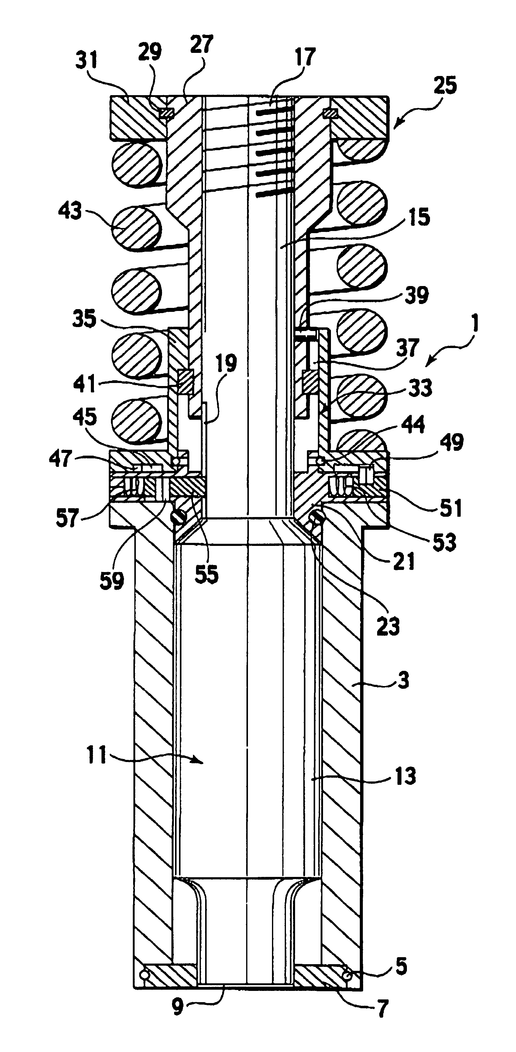
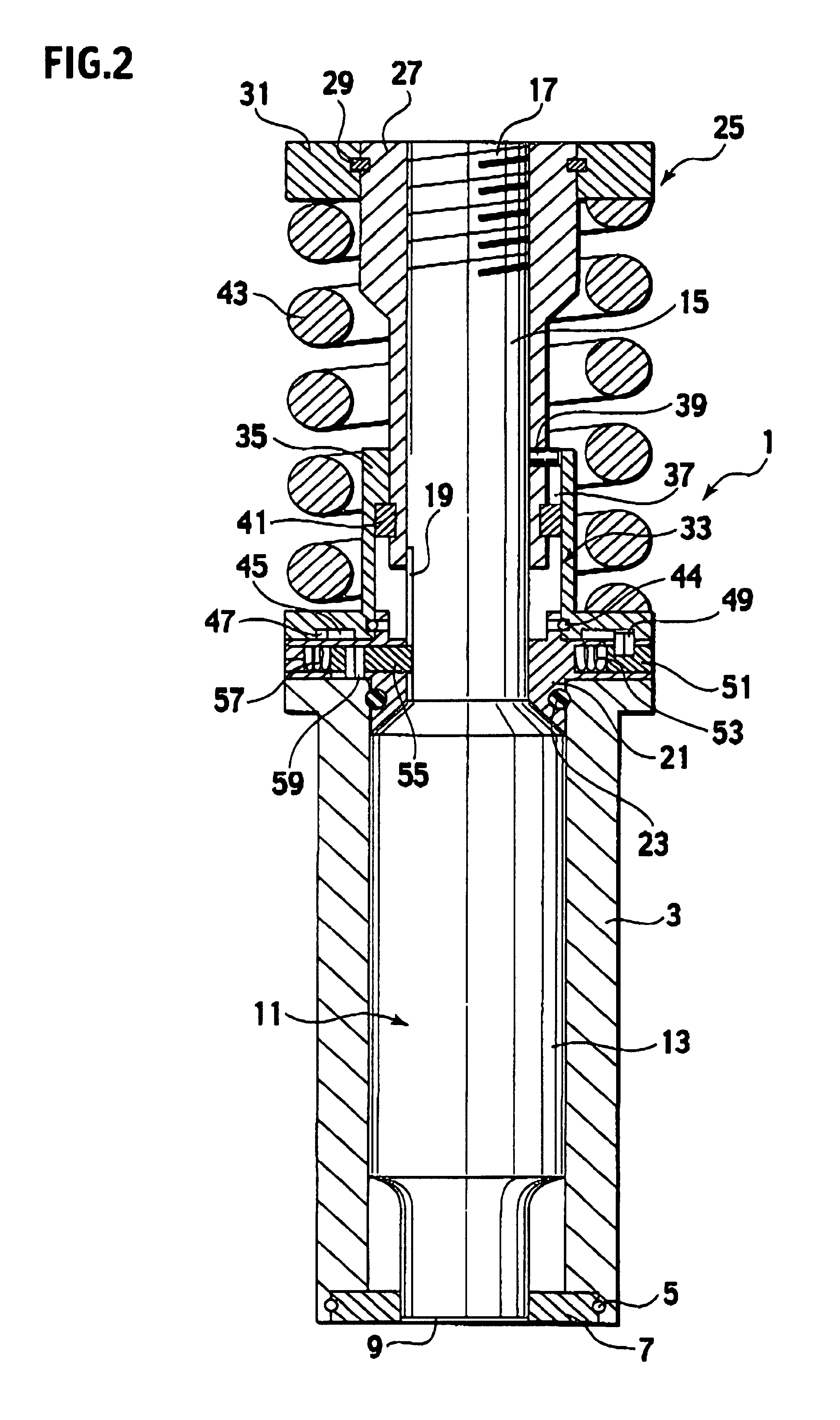
[0027] With reference to FIG. 2, an upper tool device (a die assembly) 1 according to an embodiment of the present invention includes a cylindrical punch guide 3. A stripper plate 7 is detachably attached to a lower end of the punch guide 3 through appropriate stoppers 5 such as O-rings. Alternatively, the stripper plate 7 can be formed integrally with the punch guide 3 in advance.

[0028] A punch 11 having a punch blade 9 provided on a lower end thereof is fitted into the punch guide 3 so as to be movable in vertical direction. The punch 11 is configured to include the punch blade 9 in a lower portion of a punch body 13 having a large diameter and slidably fitted into the punch guide 3. A punch driver 15 smaller in diameter than the punch body 13 is integrally provided with ...


PUM

PropertyMeasurementUnit
diameteraaaaaaaaaa
heightaaaaaaaaaa
lengthaaaaaaaaaa

Abstract

An upper tool device includes: a punch body having a punch blade at a lower end of the punch body; a punch guide into which the punch body is fitted so as to be movable in vertical direction; an adjustment screw member provided above the punch guide, the adjustment screw member screwed with a screw formed on the punch body; a stripper unit including an urging unit urging the punch body in an upward direction; and a retainer collar including a stopper piece having a tip end disengageably engaged with a stopper formed on the punch body. In the device, the stripper unit is detachably provided in the upper tool device, and the retainer collar is provided between the punch guide and the stripper unit in a manner such that the retainer collar can be relatively rotated against the stripper unit.

Description

CROSS REFERENCE TO RELATED APPLICATION [0001] This application is based upon and claims the benefit of priority from the prior Japanese Patent Application No. P2005-195092, filed on Jul. 4, 2005; the entire contents of which are incorporated herein by reference. BACKGROUND OF THE INVENTION [0002] 1. Field of the Invention [0003] The present invention relates to an upper tool device employed to be attached to a punch press such as a turret punch press and a punch employed in the upper tool device. More specifically, the invention relates to an upper tool device that can facilitate height adjustment. [0004] 2. Description of the Related Art [0005] In a conventional upper tool device employed to be attached to a punch press, when a punch blade of the upper tool device is worn, the punch blade is reground. When the punch blade is reground, an entire length of the punch is reduced, and a height adjustment is consequently performed (for example, see Patent document: Japanese Patent Applic...

Claims


Application Information

Patent Timeline
Patent Type & Authority Applications(United States)
IPC IPC(8): B26F1/14
CPCB21D45/006Y10T83/2159Y10T83/9423Y10T83/9428
Inventor ENDO, SHIGERU
Owner AMADA TOOL TECHNICA
Why Eureka
Try Eureka