Rotary feed-through with leakage sensor

a leakage sensor and rotary feed-through technology, applied in the field of rotary feed-through, can solve the problems of large leakage fluid escape, damage to the rotary feed-through,

Inactive Publication Date: 2007-02-15
OTT JAKOB & SPANNTECHN
View PDF10 Cites 24 Cited by
  • Summary
  • Abstract
  • Description
  • Claims
  • Application Information

AI Technical Summary

Benefits of technology

[0003] The invention is based on the objective of developing a rotary feed-through of the initially cited type that makes it possible to monitor the leakage fluid collected within the rotary feed-through.

Problems solved by technology

However, larger quantities of leakage fluid can escape in certain situations during operation.
This is associated with the risk of the leakage fluid backing up within the collecting chamber such that the rotary feed-through may become damaged.

Method used


Image

  • Rotary feed-through with leakage sensor
  • Rotary feed-through with leakage sensor
  • Rotary feed-through with leakage sensor

Examples


Embodiment Construction

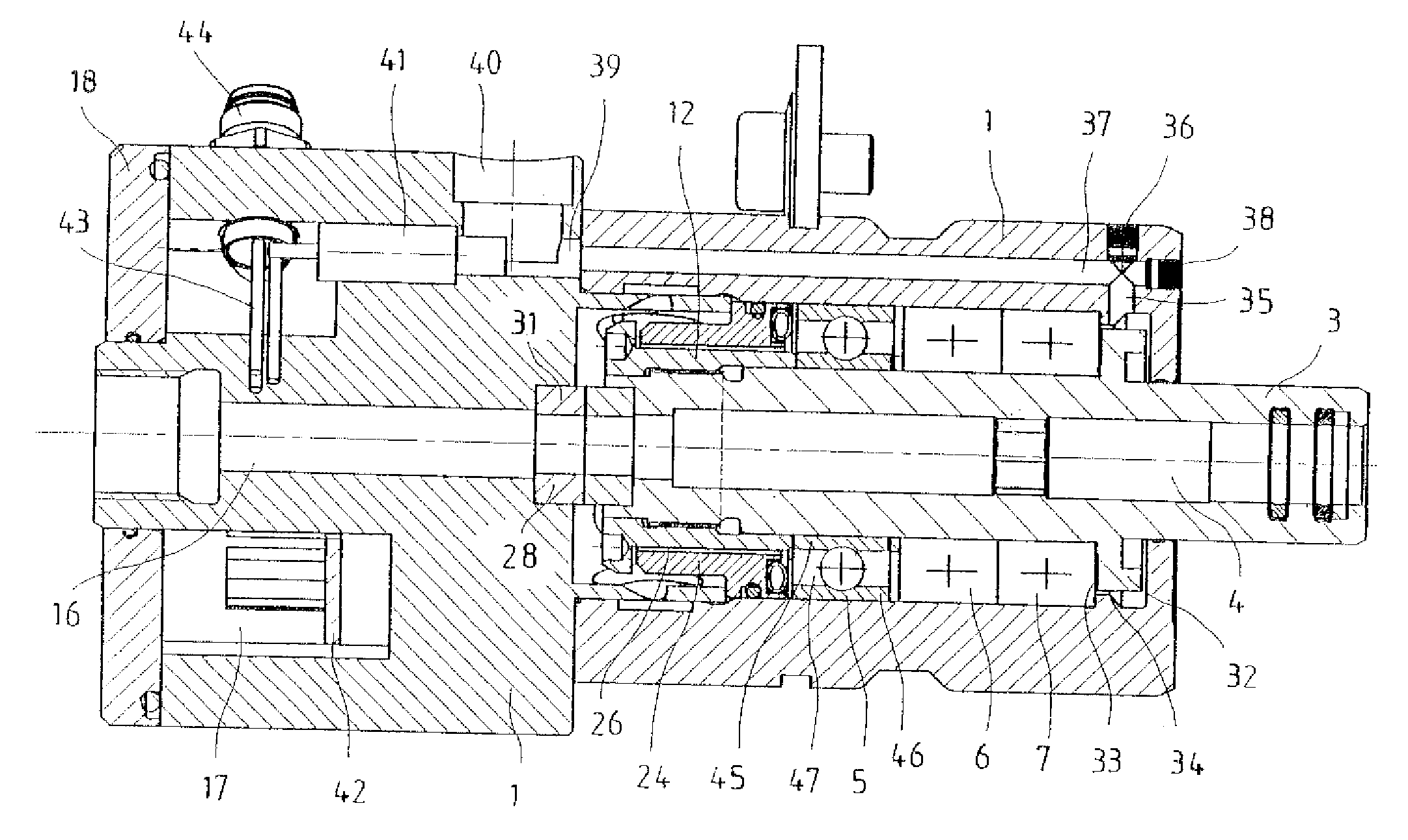
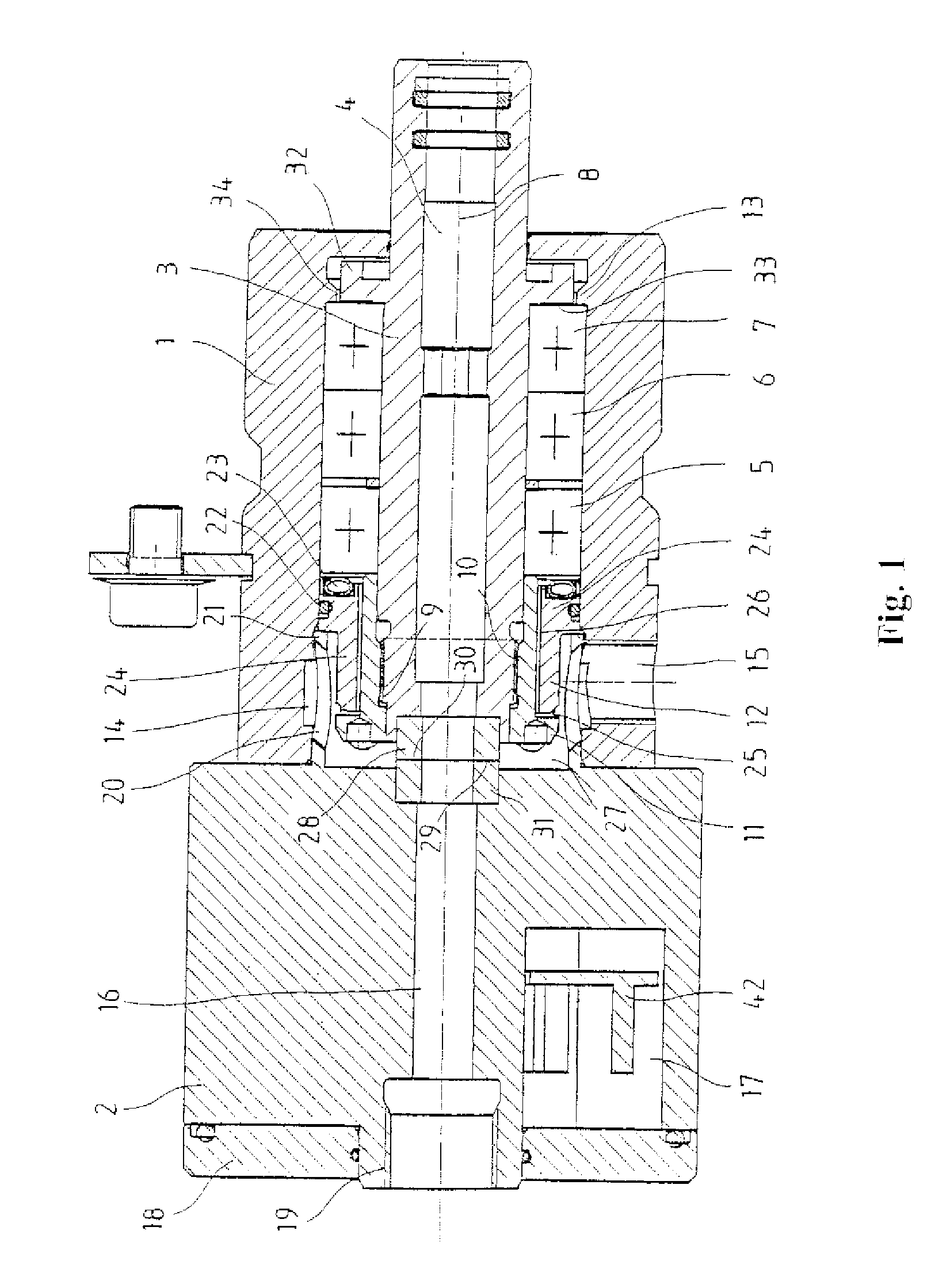
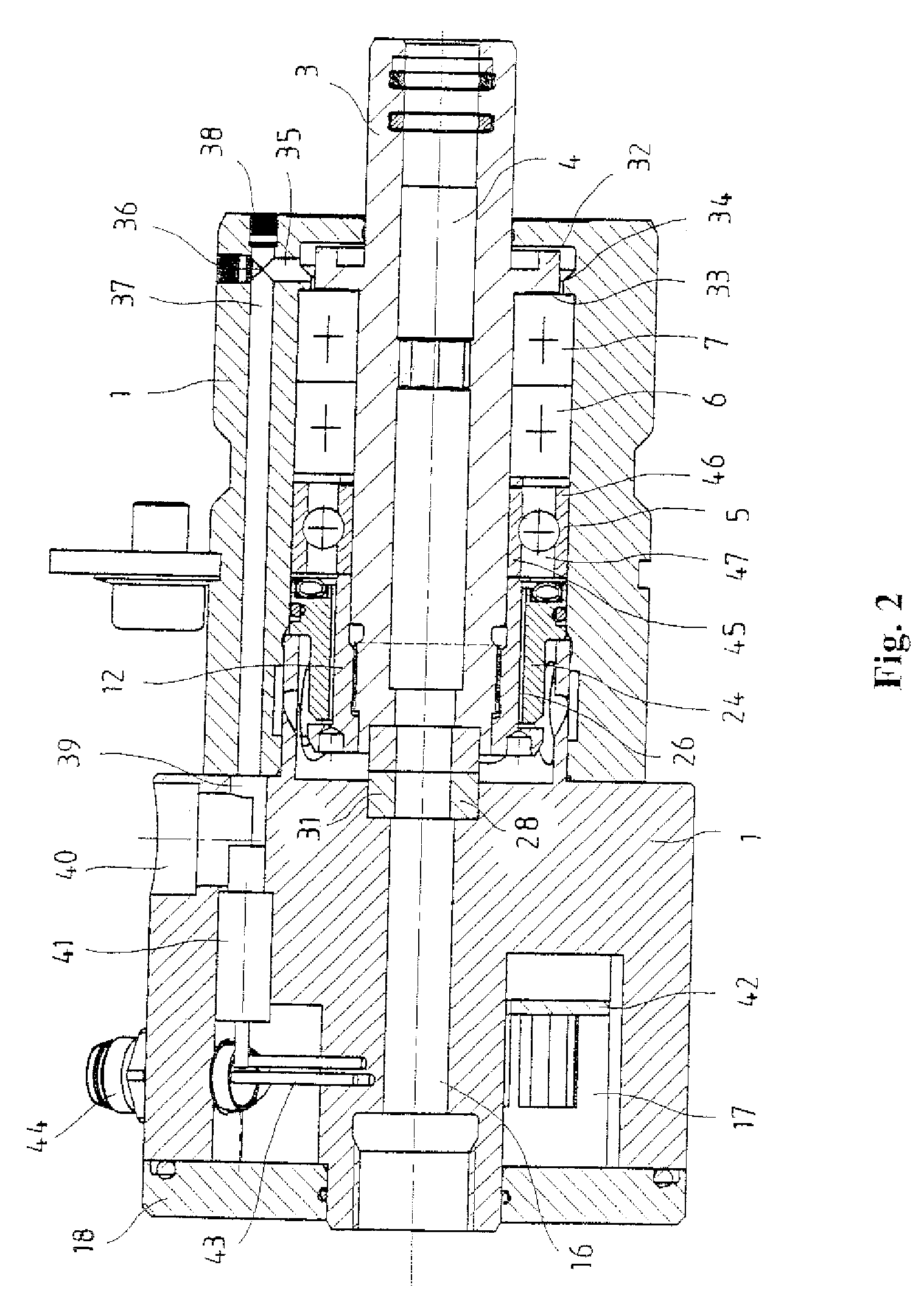
[0014] The rotary feed-through schematically illustrated in FIGS. 1 and 2 contains a housing with a front housing part 1 that is arranged on the right side in the figure and a rear housing part 2 that is tightly connected to the front housing part. A hollow shaft 3 with a central through-channel 4 is supported in the front housing part 1 by means of several successively arranged bearings 5, 6 and 7 such that it is rotatable about a central axis 8. A clamping hushing 12 provided with an internal thread 10 and an end flange 11 is screwed on an external thread 9 on the inner end of the hollow shaft 3 arranged in the housing part 1. This clamping bushing 12 prestresses the bearings 5, 6 and 7 against an annular step 13 in the interior of the housing part 1. For example, a hollow tension rod of a tool tensioner integrated into a machine tool work spindle can be inserted in a radially sealed fashion into through-channel 4 at the outer end of the hollow shaft 3 that lies on the right side ...


PUM


Abstract

The invention pertains to a rotary feed-through for supplying a fluid to a rotating machine part with a hollow shaft (3) that is rotatably supported in a housing (1, 2) and has a first sliding surface (29), with a sealing bushing (31) that is arranged in a rotationally fixed fashion within the housing (1, 2) coaxial to the shaft (3) and has a second sliding surface (30) for contacting the first sliding surface (29), and with a collecting chamber (27) that is arranged within the housing (1, 2) and serves for collecting the leakage fluid escaping between the two sliding surfaces (29, 30). The leakage fluid collected within the rotary feed-through can be monitored with the aid of a detection channel (26, 33, 34, 37, 39, 47) in the housing (1, 2) that is connected to the collecting chamber (27) and contains a leakage sensor (41).

Description

FIELD OF THE INVENTION [0001] The invention pertains to a rotary feed-through. BACKGROUND OF THE INVENTION [0002] A rotary feed-through of this type for supplying a fluid to a rotating machine part is known from DE 102 25 272 A1. This rotary feed-through features a hollow shaft that is rotatably supported within a housing and has a first sliding surface, a sealing bushing that is arranged in the housing in a rotationally fixed fashion coaxial to the hollow shaft and has a second sliding surface for contacting the sliding surface of the hollow shaft, and a collecting chamber that is arranged within the housing and in which the leakage fluid escaping between the sliding surfaces of the rotating hollow shaft and the rotationally fixed sealing bushing can be collected. This collecting chamber is connected to a leakage opening, through which the leakage fluid collected in the collecting chamber can be discharged. Since only small quantities of the fluid being conveyed through the rotary ...

Claims


Application Information

Patent Timeline
Patent Type & Authority Applications(United States)
IPC IPC(8): F16L27/08
CPCF16L27/0828G01M3/2853G01M3/183Y10T137/8326Y10T137/86268
Inventor MOHR, PETERBECHTELER, WOLFGANGGAST, STEPHANLEIDL, HANS
Owner OTT JAKOB & SPANNTECHN
Why Eureka
Try Eureka