Sound field compensating apparatus and sound field compensating method

Inactive Publication Date: 2007-02-15
SONY CORP
View PDF3 Cites 16 Cited by
  • Summary
  • Abstract
  • Description
  • Claims
  • Application Information

AI Technical Summary

Benefits of technology

[0013] According to the configuration of the one embodiment, the sound field compensating apparatus drives a speaker by using the measuring test signal and performs compensation for the characteristic of the sound field produced by the speaker through the analysis of the output from the speaker. The apparatus includes the sound-volume regulating test signal generating section that generates the sound-volume regulating test signal; the driving section that drives the speaker; the microphone that receives the output from the speaker; and the control section that processes an output signal of the microphone and that controls operations of respective sections. The sound-volume regulating test signal is the sum signal representative of the sum of the single-frequency sinusoidal wave signals whose frequencies are set to the relationship of an integer ratio. The control section causes the driving section to drive the speaker by using the sound-volume regulating test signal to thereby detect signal levels of frequency components of the sinusoidal wave signals from output signals of the microphone, and in accordance with an average value of the signal levels, sets a measuring sound volume in an event that the speaker is driven by using the measuring test signal. Thereby, the sound volume can be set without driving the speaker by using pink noise or white noise. Further, the sound-volume regulating test signal is the sum signal representative of the sum of the single-frequency sinusoidal wave signals whose frequencies are set to the relationship of an integer ratio. Thereby, the speaker can be driven in a wide frequency band reproducible by the speaker and the speaker output in a respective-frequency can be verified by setting the sinusoidal wave signals, similarly to the case of driving the speaker by using pink noise or white noise. Further, since the process is executed by using the average value, the influence of noise can be avoided, whereby the sound volume can be appropriately set.
[0014] According to the other embodiment, a sound field compensating method can be provided that, when compensating for the characteristic of the sound field by using the test signal reproduced with the speaker system, is capable of appropriately setting the sound volume without driving the speaker by using pink noise or white noise.
[0015] Consequently, as an advantage, according to the embodiments of the invention, a sound field compensating method can be provided that, when compensating for the characteristic of the sound field by using the test signal reproduced with the speaker system, is capable of appropriately setting the sound volume without driving the speaker by using pink noise or white noise.

Problems solved by technology
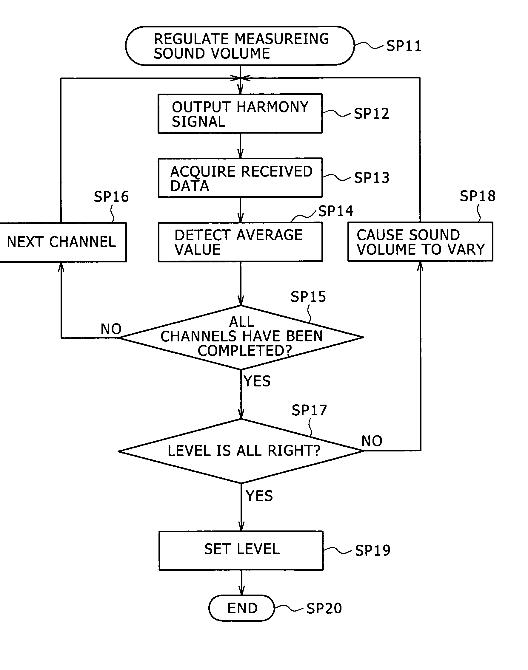
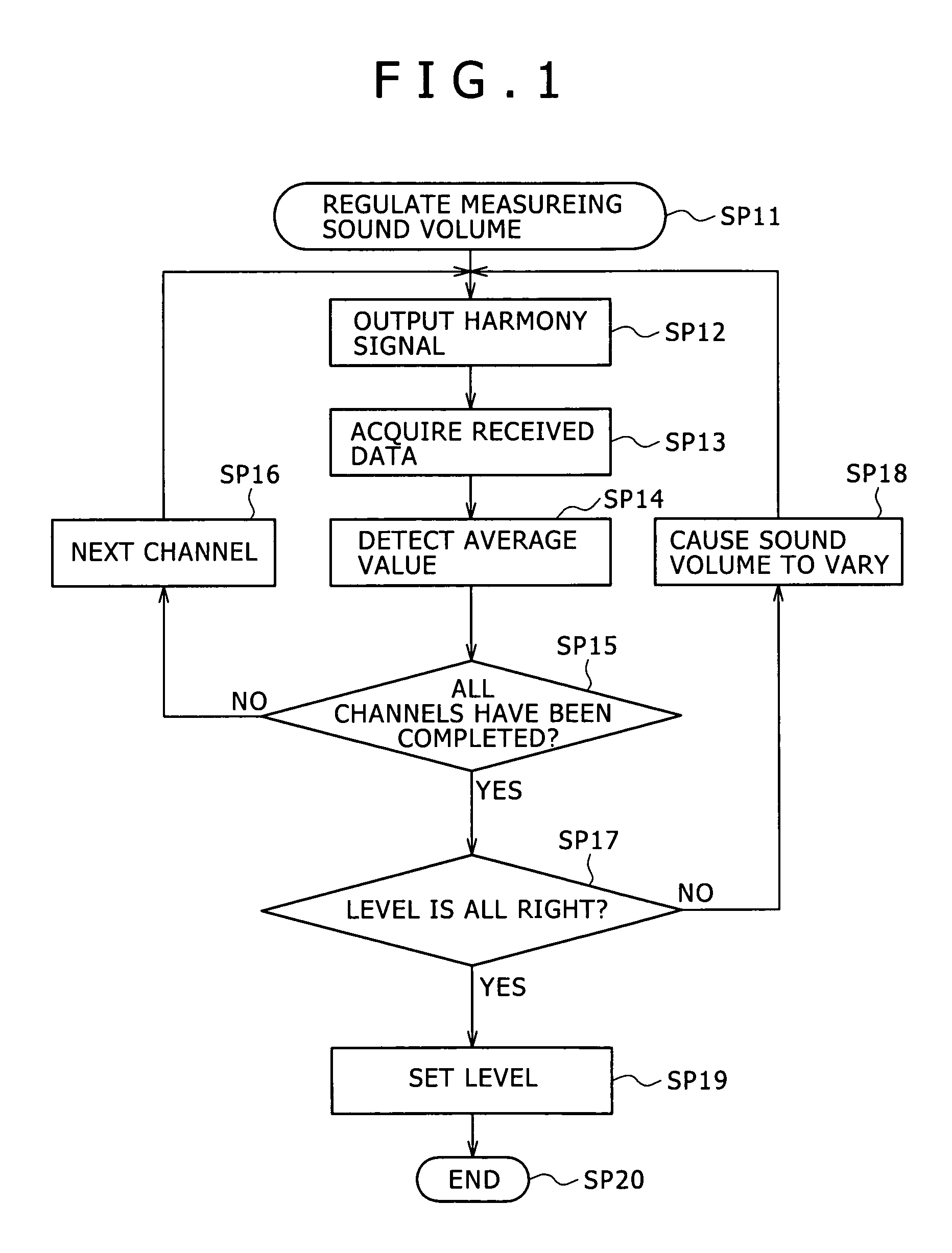
Nevertheless, however, a problem arises in that reproduction of pink noise or white noise results in the development of a very uncomfortable feeling in auditory sense for a user staying in a vehicle cabin.

Method used


Image

  • Sound field compensating apparatus and sound field compensating method
  • Sound field compensating apparatus and sound field compensating method
  • Sound field compensating apparatus and sound field compensating method

Examples


first embodiment

[0025] (1) Configuration of Embodiment

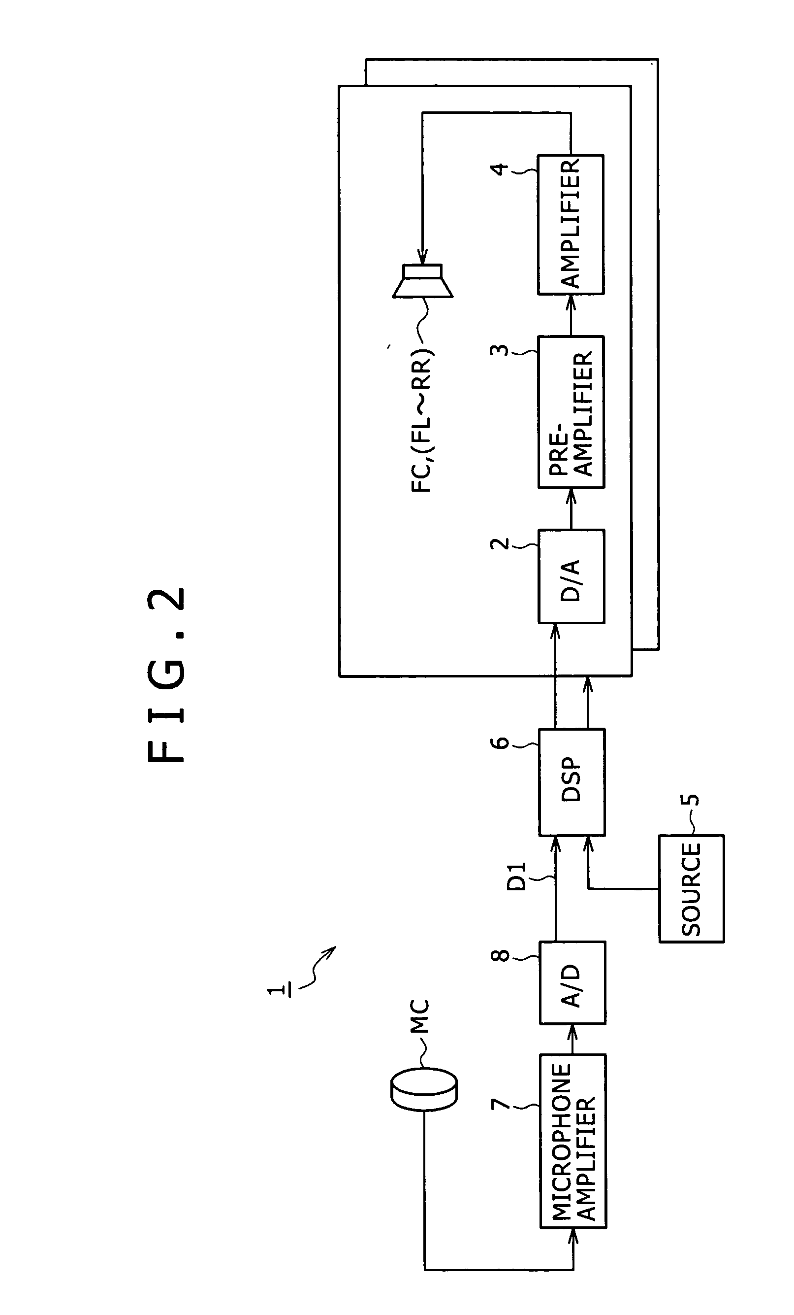
[0026]FIG. 2 is a block diagram showing an in-vehicle audio system 1 according to a first embodiment of the invention, and FIG. 3 is a plan view showing a speaker system of the in-vehicle audio system 1. The in-vehicle audio system 1 provides a user with music contents through 5.1 channels. With reference to FIG. 3, in the in-vehicle audio system 1, a speaker FC corresponding to a front center channel is provided in a front and central portion of a front seat. Speakers FR and FL corresponding to front right and left channels are provided to front right and left doors, respectively. On the rear side, speakers RL and RR corresponding to rear right and left channels are provided to rear right and left doors, respectively. In addition, a subwoofer RC is provided to a rear, central portion of a rear seat. A microphone MC for picking up outputs of the speakers FC, FL, FR, RL, and RR is disposed near a portion where the head of a driver is placed on a...

second embodiment

[0056] In a second embodiment, the sound-volume regulating test signal according to the first embodiment described above is used also for the connection-verifying test signal described above in conjunction with step SP2 shown in FIG. 4. Further, also in the connection-verifying process, the frequency of the test signal is shifted in conjunction with shifting of the drive system for the speaker.

As such, the above-described processes of steps SP2 and SP3 shown in FIG. 4 can be synchronously executed.

[0057] According to the second embodiment, the sum signal representative of the sum of single-frequency sinusoidal wave signals whose frequencies are set to the relationship of an integer ratio used for the connection-verifying test signal. Thereby, the configuration of the digital signal processor 6 can be simplified.

Further, driving of the speaker by using the connection-verifying test signal can be implemented without being recognized by the user.

third embodiment

[0058] The first, although second embodiment has been described with reference to the case where the invention is adapted to the 5.1-channel audio system, the invention is not limited thereto. The invention can be widely adapted to multichannel audio systems with various other numbers of channels.

[0059] Further, although the first, second embodiment has been described with reference to the case where the frequency characteristics and delay times of the plurality of channels are collectively regulated by the digital signal processor, the invention is not limited thereto. The invention can be widely adapted even to the case where the regulation is executed in units of the channel.

[0060] Further, although the first, second embodiment has been described with reference to the case where the invention is adapted to the in-vehicle audio system and the sound field is compensated for, the invention is not limited thereto. The invention can be widely adapted even to the case where the inven...


PUM


Abstract

The sound field compensating apparatus includes a section that generates sound-volume regulating test signal; a driving section that drives a speaker; a microphone that receives the output from the speaker; and a control section that processes an output signal of the microphone and that controls operations of respective sections. The sound-volume regulating test signal is a sum signal representative of the sum of single-frequency sinusoidal wave signals whose frequencies are set to the relationship of an integer ratio. The control section causes the driving section to drive the speaker by using the sound-volume regulating test signal to thereby detect signal levels of frequency components of the sinusoidal wave signals from output signals of the microphone. In accordance with an average value of the signal levels, the control section sets a measuring sound volume when the speaker is driven by using the measuring test signal.

Description

CROSS REFERENCES TO RELATED APPLICATIONS [0001] The present invention contains subject matter related to Japanese Patent Application JP 2005-232953 filed in the Japanese Patent Office on Aug. 11, 2005, the entire contents of which being incorporated herein by reference. BACKGROUND OF THE INVENTION [0002] 1. Field of the Invention [0003] The present invention relates to a sound field compensating apparatus and a sound field compensating method, and can be adapted to, for example, an in-vehicle audio system (or, a car audio system). More specifically, the invention relates to a technique in which, when compensating for sound field characteristics by reproducing a test signal through a speaker system, a speaker is driven by a sound-volume regulating test signal formed of a sum signal representative of the sum of single-frequency sinusoidal wave signals whose frequencies are set to the relationship of an integer ratio, and an output signal from the speaker is detected in accordance with...

Claims


Application Information

Patent Timeline
IPC IPC(8): H04R29/00
CPCH04R29/00
Inventor OKUNO, MASAHIROKINO, YASUYUKISAWASHI, TOKIHIKOKOBAYASHI
Owner SONY CORP
Why Eureka
Try Eureka