Radio tag communication apparatus

a communication apparatus and radio tag technology, applied in the direction of electromagnetic wave modulation, near-field system using receivers, modulation, etc., can solve the problems of inability to communicate between the communication apparatus and the radio rag, high production cost, and complicated construction, so as to achieve good communication, broaden the signal transmission range, and facilitate the transmission.

Inactive Publication Date: 2007-02-15
BROTHER KOGYO KK
View PDF14 Cites 26 Cited by
  • Summary
  • Abstract
  • Description
  • Claims
  • Application Information

AI Technical Summary

Benefits of technology

[0008] It is therefore an object of the present invention to provide a radio tag communication apparatus that can well communicate with a radio tag as a communication destination. It is another object of the present invention to provide a radio tag communication apparatus that has a broad communicable range and / or a simple construction.

Problems solved by technology

However, the above-indicated conventional system has drawbacks that its construction is complicated and its production cost is considerably high.
Therefore, when a radio tag communication apparatus and a radio tag communicate with each other while they are moving relative to each other, it is possible that the radio tag may go out of the communicable range of the communication apparatus and accordingly the communication between the communication apparatus and the radio rag may fail.
Thus, there has not been developed such a radio tag communication apparatus that can well communicate with a radio tag as a communication destination, irrespective of a relative-positional relationship between them or a communication environment around them.

Method used


Image

  • Radio tag communication apparatus
  • Radio tag communication apparatus
  • Radio tag communication apparatus

Examples


embodiment 1

[0049] EMBODIMENT 1

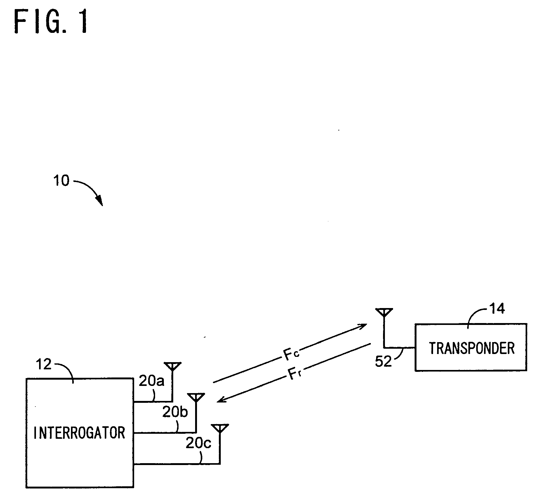
[0050]FIG. 1 is a view for explaining an arrangement of a communication system 10 to which the present invention is applied. The communication system 10 is a so-called RFID (radio frequency identification) system, and includes a radio tag communication apparatus 12 as an embodiment of the present invention, and a single, or a plurality of, radio tags 14 (a single radio tag 14 is shown in FIG. 1). The radio tag communication apparatus 12 functions as an interrogator of the RFID system 10, and the radio tag 14 functions as a transponder of the same 10. More specifically described, if the radio tag communication apparatus 12 transmits an interrogator wave (i.e., a transmission signal), Fc, toward the radio tag 14, then the radio tag 14 receives the interrogator wave Fc, modulates, based on an information signal (i.e., “data”), the received interrogator wave Fc, and returns the modulated interrogator wave Fc as a transponder wave (i.e., a return signal), Fr, toward th...

embodiment 2

[0071] EMBODIMENT 2

[0072] Hereinafter, there will be described a second embodiment of the present invention by reference to FIGS. 7 and 8. The same reference numerals as used in the first embodiment shown in FIGS. 1 through 6 are used to designate the corresponding elements or parts of the second embodiment, and the description thereof is omitted.

[0073]FIG. 7 shows the second embodiment in which the three bar-like transmission-reception antenna elements 20a, 20b, 20c extend parallel to each other, and are provided on a common plane. The signal transmission range within which the transmission-reception antenna element 20a can transmit the transmission signal is a cylindrical space, A, having a centerline on an axis line of the antenna element 20a; the signal transmission range within which the transmission-reception antenna element 20b can transmit the transmission signal is a cylindrical space, B, having a centerline on an axis line of the antenna element 20b; and the signal transm...

embodiment 3

[0075] EMBODIMENT 3

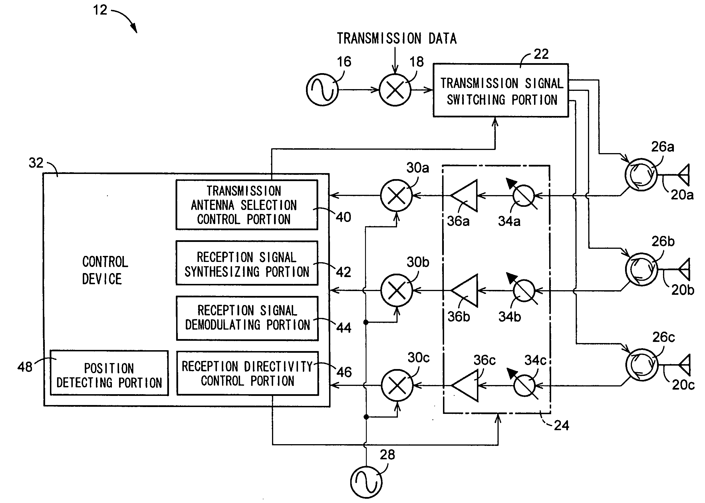
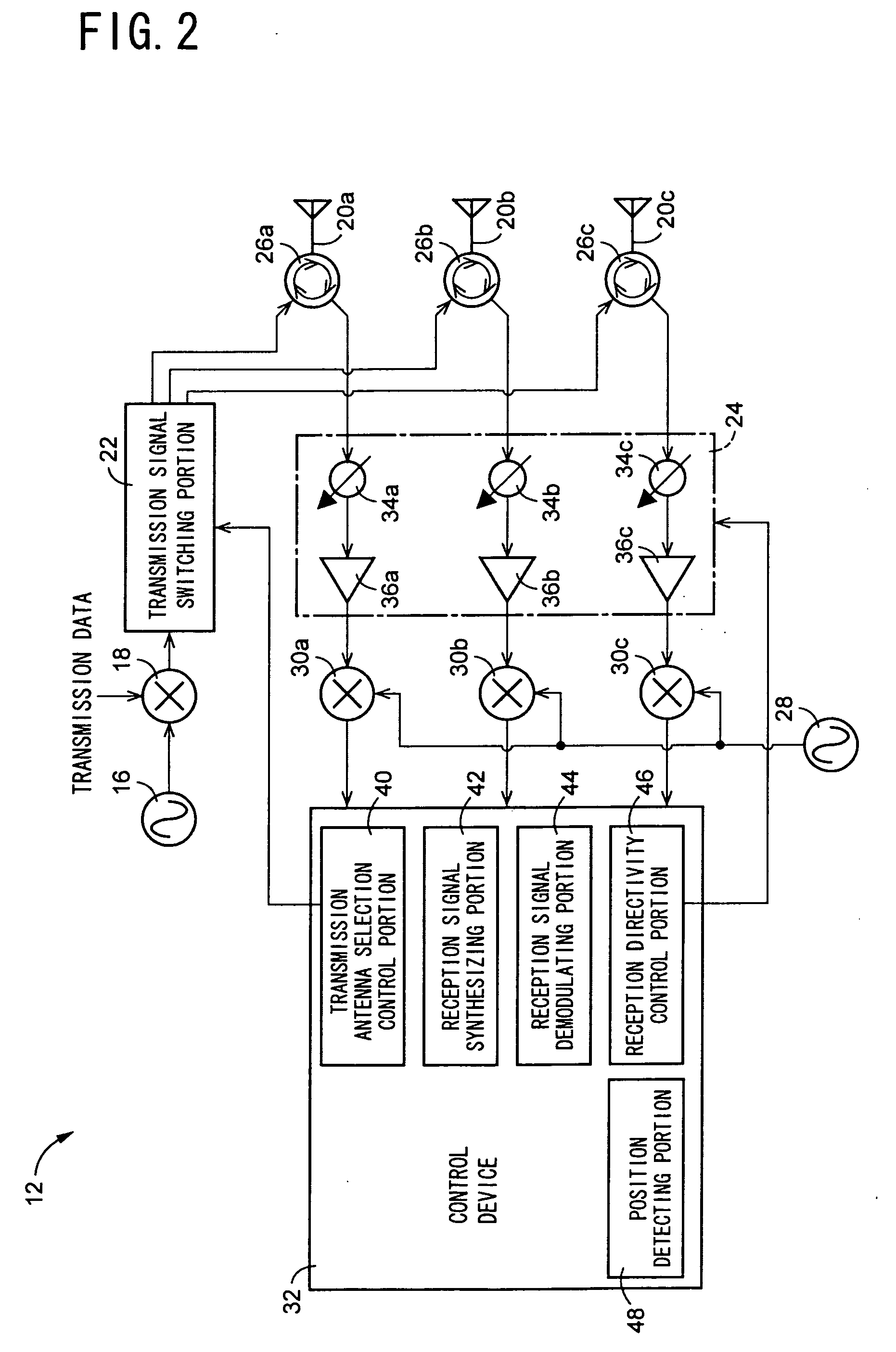
[0076]FIG. 9 is a view for explaining an electrical arrangement of a radio tag communication apparatus 66 as a third embodiment of the present invention. As shown in the FIG., the radio tag communication apparatus 66 includes twelve transmission-reception antenna elements 20a, 20b, 20c, . . . , 20l (hereinafter, simply referred to as the transmission-reception antenna elements 20 unless they need to be discriminated from each other) each of which is provided by a bar-like antenna element such as a dipole antenna; a transmission antenna element selecting portion 68 that switches the circuit so as to supply the transmission signal generated by the transmission signal generating portion 18 to one of the twelve transmission-reception antenna elements 20; a reception antenna element selecting portion 70 that switches the circuit so as to supply the respective reception signals received by two or more of the twelve transmission-reception antenna elements 20 to the phase...


PUM

PropertyMeasurementUnit
angleaaaaaaaaaa
transmissionaaaaaaaaaa
weightsaaaaaaaaaa

Abstract

A radio tag communication apparatus having a broad communicable range and a simple arrangement, is provided. Since there are provided a transmission antenna selection control portion for selecting a single transmission-reception antenna element to transmit a transmission signal, from a plurality of transmission-reception antenna elements, and a reception signal synthesizing portion for synthesizing respective reception signals received by the plurality of transmission-reception antenna elements, with each other, a communicable range of the radio tag communication apparatus can be broadened by transmitting the transmission signal from a diversity antenna having a simple arrangement, and a reception sensitivity of the radio tag communication apparatus can be enhanced by synthesizing the reception signals received by the plurality of transmission-reception antenna elements, with each other.

Description

[0001] The present application is a continuation-in-part application derived from a national phase of an international patent application PCT / JP2005 / 005498 filed on Mar. 25, 2005, the contents of which are incorporated herein by reference.BACKGROUND OF THE INVENTION [0002] 1. Field of the Invention [0003] The present invention relates to a radio tag communication apparatus that communicates with a radio tag in and from which information can be written and read by radio, and particularly to the art of broadening a communicable range of the radio tag communication apparatus. [0004] 2. Related Art Statement [0005] There is known an RFID (radio frequency identification) system including a radio tag (i.e., a transponder) that has certain information stored therein, and a radio tag communication apparatus that reads, by radio, the information from the radio tag. Even if the radio tag may be stained, or located at an invisible place, the radio tag communication apparatus can communicate wi...

Claims


Application Information

Patent Timeline
Patent Type & Authority Applications(United States)
IPC IPC(8): H04B1/02H04Q5/22H01B7/06H01B7/10H04B1/59H04B5/02H04B7/04
CPCH04B7/04
Inventor NAGAI, TAKUYAKIYOHARA, YUJI
Owner BROTHER KOGYO KK
Why Eureka
Try Eureka