Crankshaft decoupler

Active Publication Date: 2007-02-15
LITENS AUTOMOTIVE INC
View PDF6 Cites 68 Cited by
  • Summary
  • Abstract
  • Description
  • Claims
  • Application Information

AI Technical Summary

Benefits of technology

[0007] According to one aspect of the invention there is provided, a decoupler assembly for transferring rotational torque between a drive shaft and an endless drive element of an automotive engine. The decoupler assembly comprises a drive hub configured to be fixedly secured to the drive shaft. A pulley is rotatably mounted on the drive hub and adapted to be drivingly engaged with the endless drive element. A spring shell is operatively coupled between the drive hub and the pulley for selective rotation therewith. A biasing member elastically couples the spring shell

Problems solved by technology

Internal combustion engines operate as a pulse system, constantly accelerating and decelerating and causing engine vibrations.
This can result in unacceptable levels of noise and vibration along with reduced accessory drive component durability due to high fluctu

Method used


Image

  • Crankshaft decoupler
  • Crankshaft decoupler
  • Crankshaft decoupler

Examples


Embodiment Construction

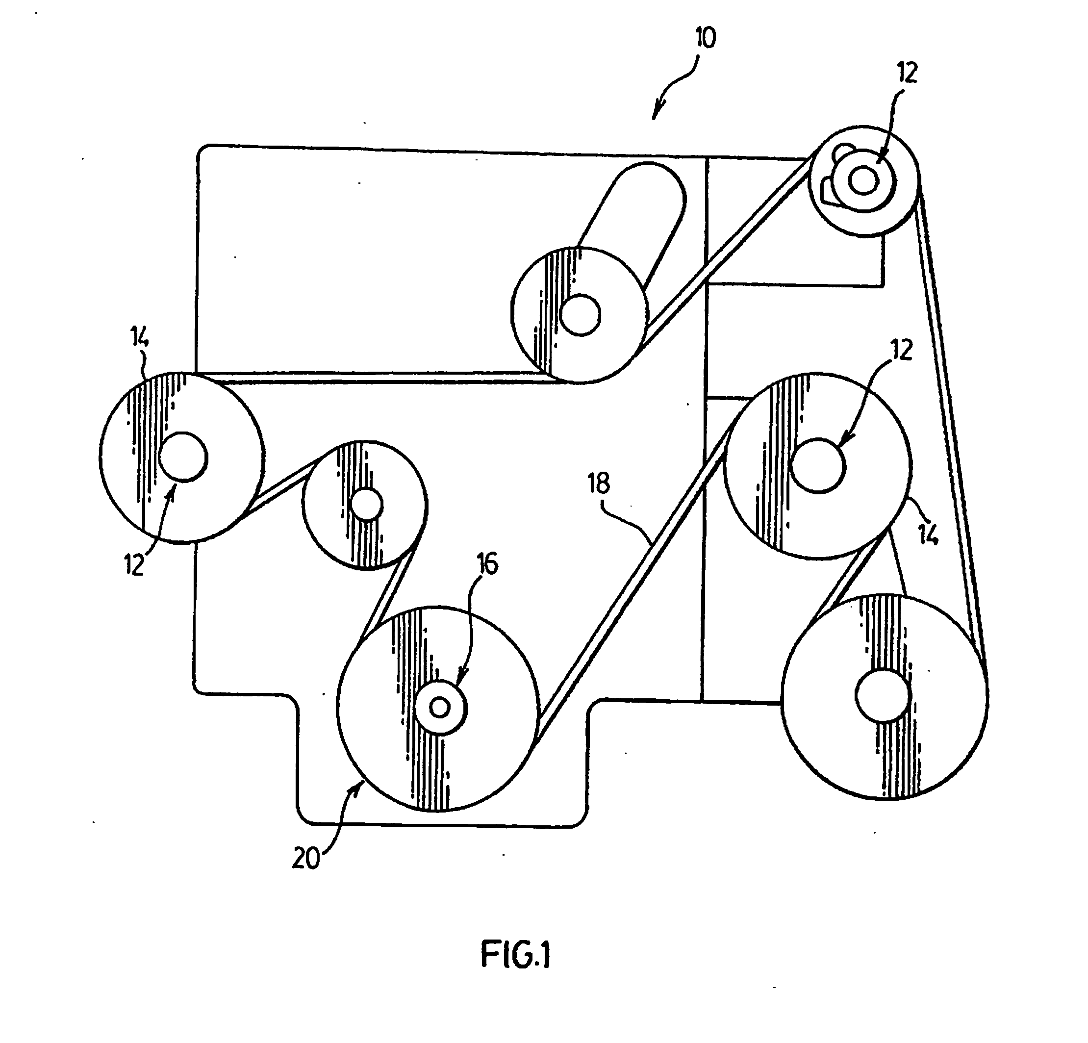
[0020] Referring to FIG. 1, an internal combustion engine for an automotive vehicle is generally indicated at 10. The engine 10 includes a plurality of belt driven accessory components 12, such as an alternator, compressor, etc. A pulley 14 is operatively coupled to each of the belt driven accessory components 12 for driving the components 12 via rotation of the pulley 14. The engine 10 also includes a crankshaft 16, which generally provides the mechanical torque output resulting from the operation of the engine 10. An endless serpentine belt 18 is seated about each pulley 14 of the belt driven accessory components 12. The belt 18 is driven in a driven direction by the rotation of the crankshaft 16, which causes rotation of the pulleys 14. A crankshaft torque modulator or decoupler assembly 20 is operatively coupled between the crankshaft 16 and the belt 18.

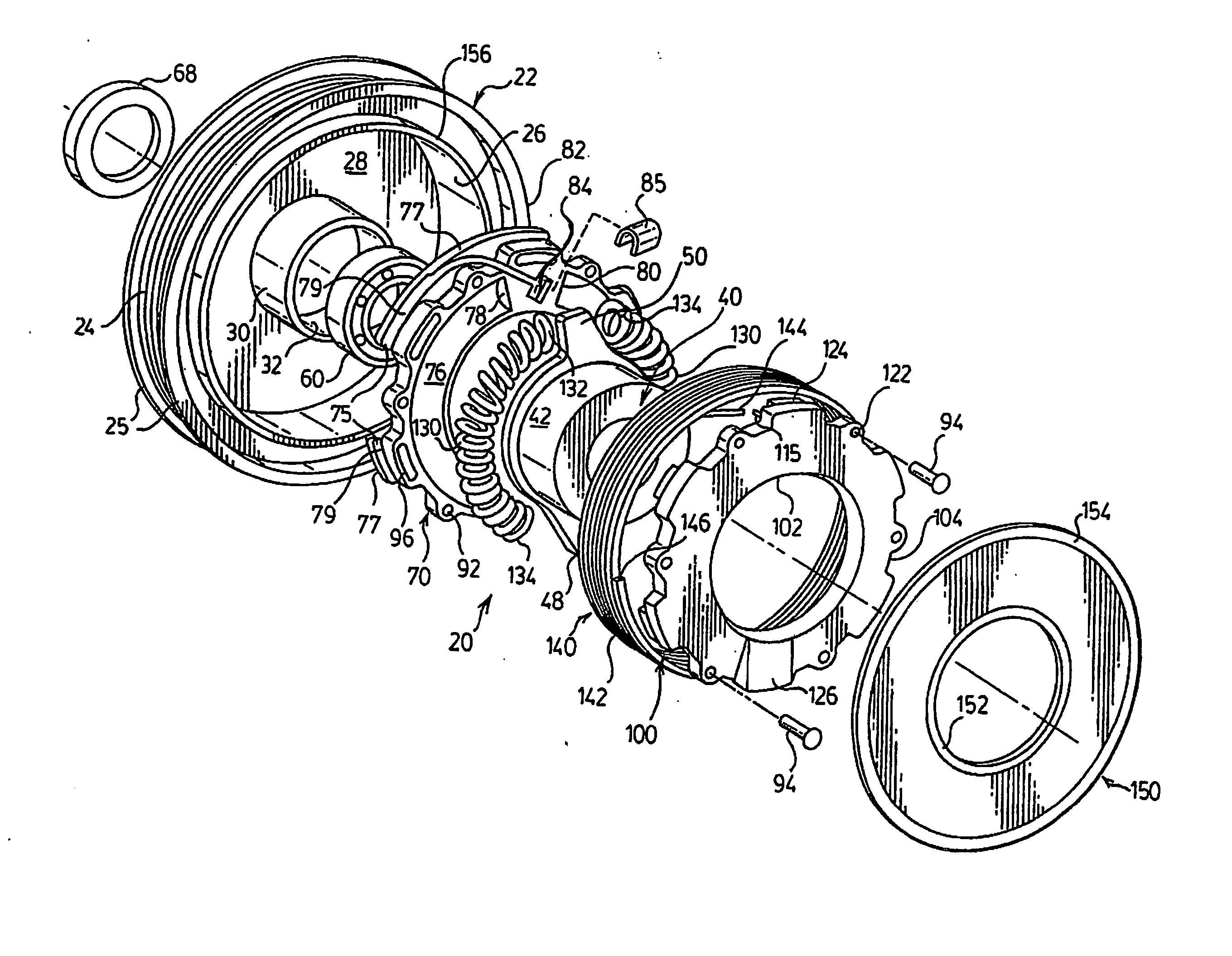
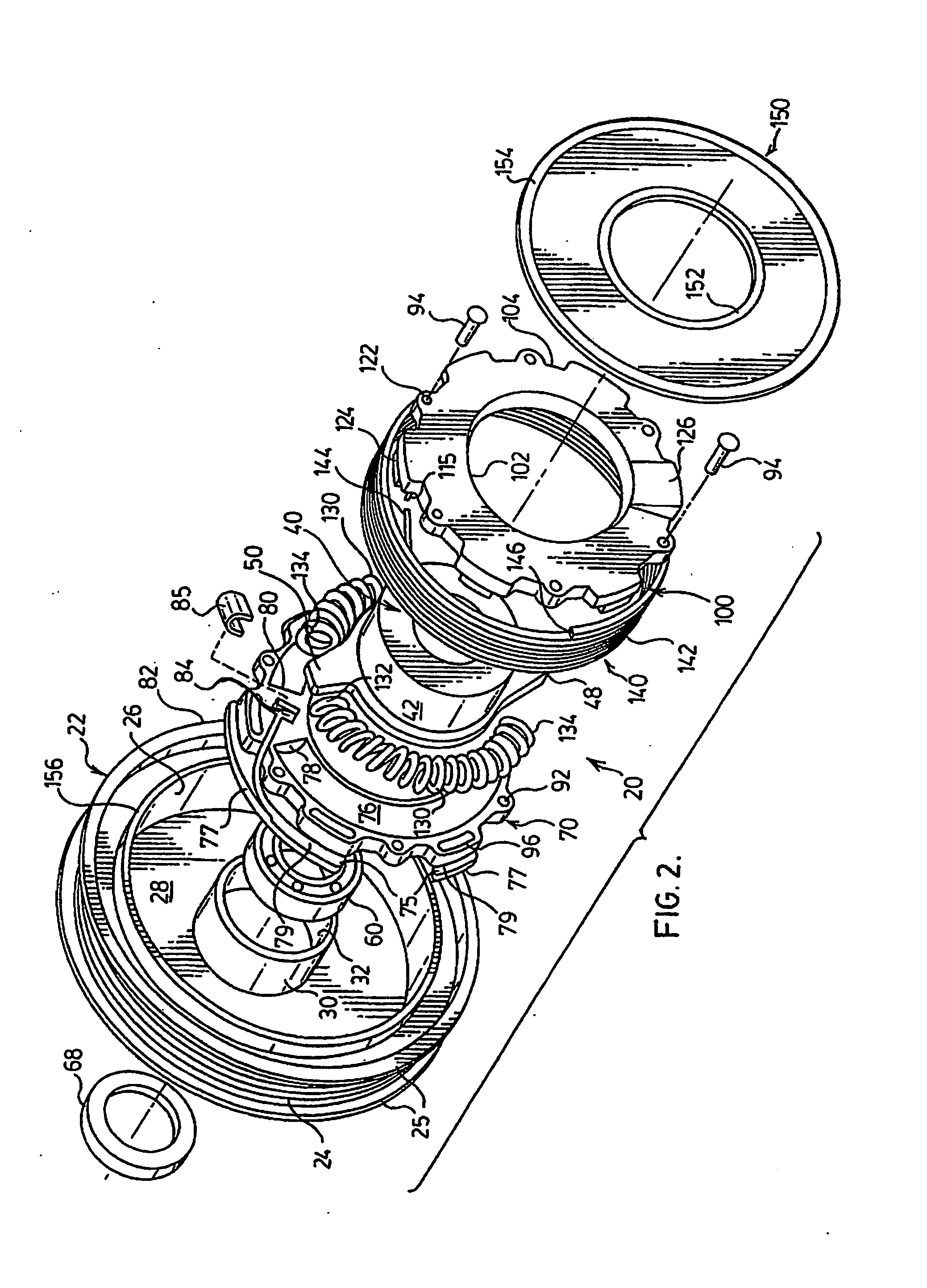
[0021] Referring to FIG. 2, the decoupler assembly 20 is shown in an exploded view and includes an output pulley 22 having an ...


PUM


Abstract

A decoupler assembly (20) is provided for transferring rotational torque between a drive shaft (16) and a drive belt (18) of an automotive engine. The decoupler assembly includes a drive hub (40) configured to be fixedly secured to the drive shaft. A pulley (22) is rotatably coupled to the drive hub (40) and adapted to be drivingly engaged with the belt (18). A spring shell (70, 100) is operatively coupled between the drive hub and the pulley for selective rotation therewith and a biasing member (130) is operatively coupled between the spring shell and the drive hub for isolating oscillatory vibrations between the drive hub and the pulley caused by rotation of the drive shaft. A clutch element (140) is seated between the spring shell (70, 100) and the pulley (22) for selectively transferring rotational torque from the drive hub to the pulley. The pulley (22) includes an inner clutch surface (26) and the clutch element includes a plurality of coils in frictional engagement with the inner clutch surface and an end coupled to the spring shell for expanding the coils against the inner clutch surface upon rotation of the spring shell with the drive hub to selectively transfer torque between the drive hub (40) and the pulley (22).

Description

BACKGROUND OF THE INVENTION [0001] The invention relates to a crankshaft and drive assembly of an automotive vehicle, and more particularly, to a decoupling assembly that allows the drive assembly to overrun or operate temporarily at a speed different from that of the crankshaft and to decouple or mechanically isolate the drive assembly from the crankshaft and reduce torsional vibrations therebetween. DESCRIPTION OF THE RELATED ART [0002] It is widely known in an automotive vehicle engine to transfer a portion of the engine output to a plurality of belt driven accessory components utilizing an endless serpentine belt. Typically, each belt driven accessory component includes a pulley drivingly engaged with the belt and the belt is driven by an output pulley coupled directly to the crankshaft. [0003] Internal combustion engines operate as a pulse system, constantly accelerating and decelerating and causing engine vibrations. As a result of these changing speeds, the belt driven access...

Claims


Application Information

Patent Timeline
IPC IPC(8): F16H61/00F16H55/14B62M9/00F16D7/02F16D13/12F16D43/26F16F15/123F16H55/36
CPCF16D7/022F16D13/12F16D43/26F16H2055/366F16H55/14F16H55/36F16F15/123F16D7/00F16D13/10F16D43/00
Inventor MEVISSEN, BERTDELL, JAMES W.ANTCHAK, JOHN R.
Owner LITENS AUTOMOTIVE INC
Why Eureka
Try Eureka