
Method for providing for Quality of Service (QoS) - based handling of IP-flows in a wireless point to multi-point transmission system

a wireless point-to-multi-point transmission system and quality of service technology, applied in the field of telecommunications, can solve the problems of low qos characteristics of wireless broadband access systems, and high bit error rates of wireless networks

Inactive Publication Date: 2007-02-15
INTELLECTUAL VENTURES I LLC
View PDF99 Cites 37 Cited by
  • Summary
  • Abstract
  • Description
  • Claims
  • Application Information

AI Technical Summary

Benefits of technology

The system provides efficient bandwidth utilization and optimal QoS, ensuring reliable and timely data transmission for various traffic types, enhancing the end-user experience by prioritizing latency and jitter-sensitive flows and managing network resources dynamically.

Problems solved by technology

Wireless networks present particular challenges over their wireline counterparts in delivering QoS.
For example, wireless networks traditionally exhibit high bit error rates (BER) due to a number of reasons.
Therefore, circuit switched connections use communications bandwidth rather inefficiently.
Conventionally, one of the barriers to the deployment of wireless broadband access systems has been the absence of acceptable QoS characteristics, while at the same time delivering bandwidth sufficient to qualify as broadband.
Delivery of raw bandwidth over wireless media without acceptable QoS would not benefit end users.
Likewise, the delivery of a high level of QoS at the cost of sufficient bandwidth would also not benefit end users.
Conventional efforts to provide wireless broadband access systems have not granted sufficient priority to QoS as a guiding principle in architecting the wireless systems, resulting in sub-optimal designs.

Method used


Image

  • Method for providing for Quality of Service (QoS) - based handling of IP-flows in a wireless point to multi-point transmission system
  • Method for providing for Quality of Service (QoS) - based handling of IP-flows in a wireless point to multi-point transmission system
  • Method for providing for Quality of Service (QoS) - based handling of IP-flows in a wireless point to multi-point transmission system

Examples


Embodiment Construction

I. An Example Environment

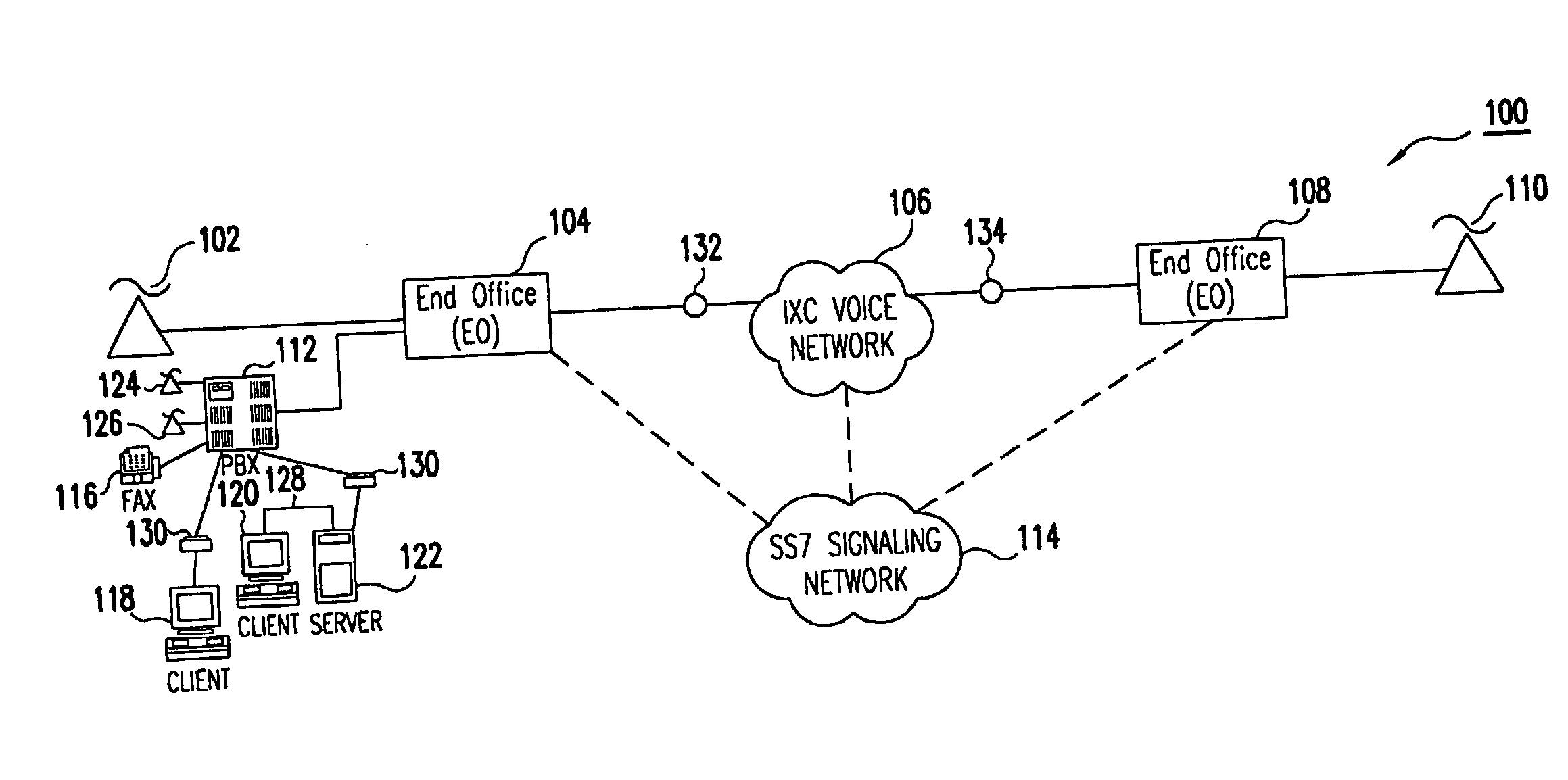
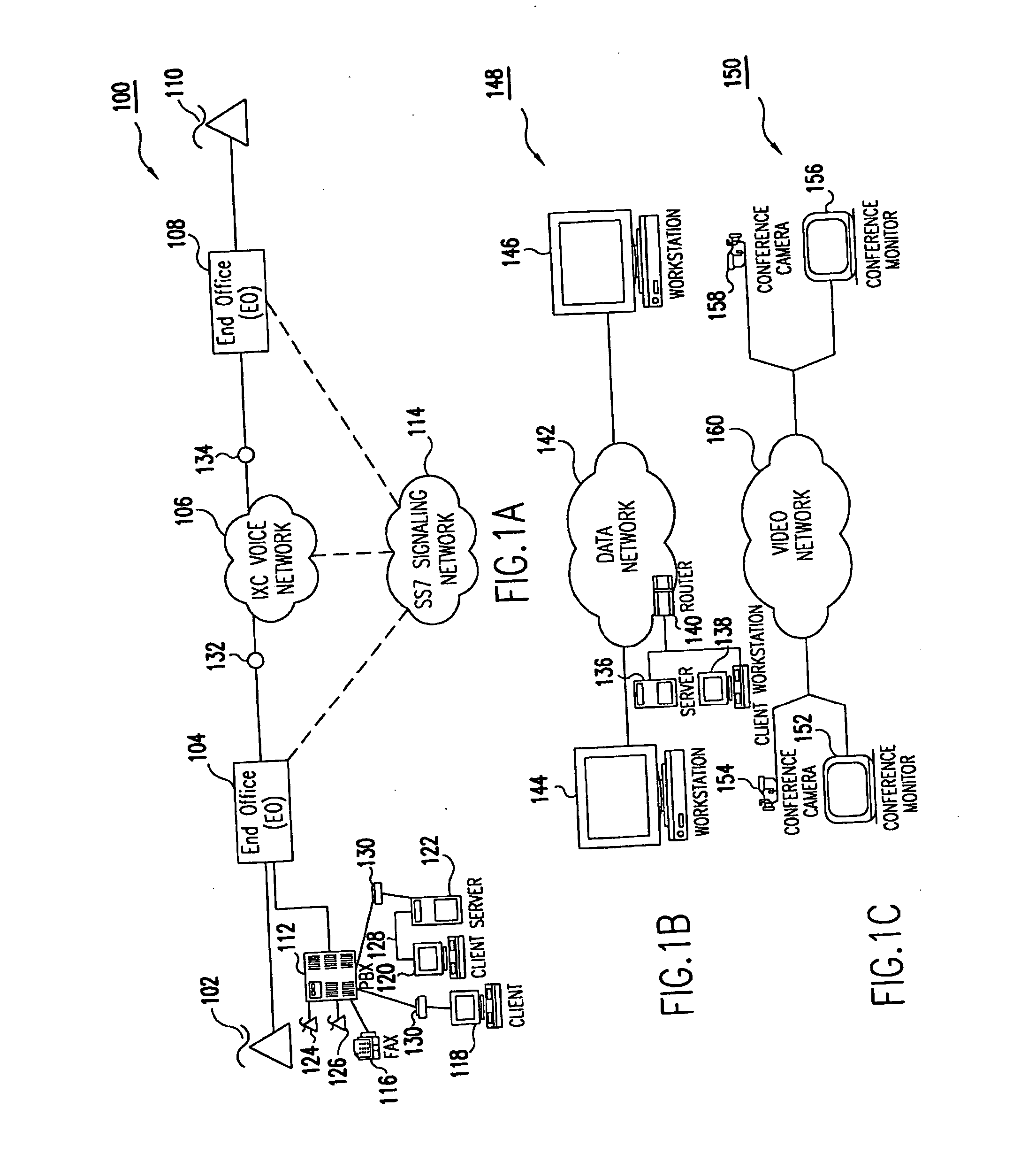
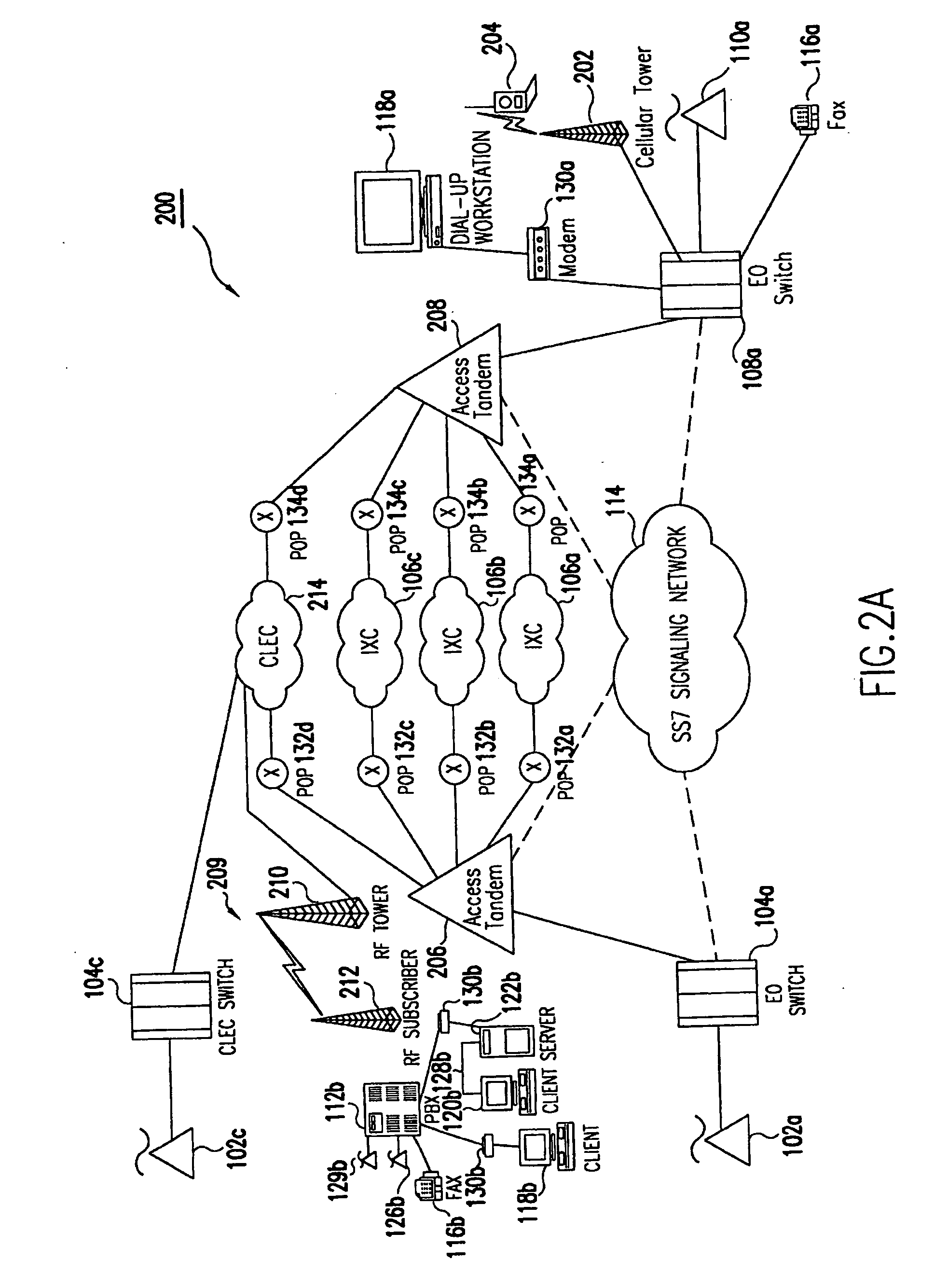
[0085] The present invention is described in terms of an example environment. The example environment uses a fixed wireless point-to-multi-point (PtMP) connection to transmit packetized data information including for example, IP telephony, video, data, received from a telecommunications carrier. As used herein, a telecommunications carrier can include US domestic entities (see Definitions below at section II) such as, e.g., ILECs, CLECs, IXCs, NGTs and Enhanced Service Providers (ESPs), as well as global entities such as PTTs and NEs, recognized by those skilled in the art. In addition, as used herein a telecommunications system includes domestic systems used by entities such as, e.g., ILECs, CLECs, IXCs and Enhanced Service Providers (ESPs), as well as global systems recognized by those skilled in the art.

[0086] In the preferred embodiment, the traffic arrives from a wide area network (WAN) connection.

[0087] Data traffic is received from a data network th...


PUM


Abstract

A method for providing quality of service (QoS) aware, wireless point to multi-point telecommunications in a telecommunications system. The telecommunications system includes: a wireless base station coupled to a first data network; one or more host workstations coupled to the first data network; one or more subscriber customer premise equipment (CPE) stations in wireless communications with the wireless base station over a shared bandwidth using a packet-centric protocol; one or more subscriber workstations coupled to each of the subscriber CPE stations over a second network. The method includes allocating shared bandwidth among the subscriber CPE stations in a manner to optimize end-user QoS. The method includes analyzing and scheduling IP flows over the shared wireless bandwidth. This includes identifying the IP flows; characterizing the IP flows; classifying the IP flows; and prioritizing the IP flows.

Description

CROSS-REFERENCE TO RELATED APPLICATIONS [0001] This application is a continuation of currently pending U.S. application Ser. No. 11 / 068,719, filed Feb. 28, 2005, entitled TRANSMISSION CONTROL PROTOCOL / INTERNET PROTOCOL (TCP / IP) PACKET-CENTRIC WIRELESS POINT TO MULTI-POINT (PtMP) TRANSMISSION SYSTEM ARCHITECTURE, which is a continuation of U.S. application Ser. No. 09 / 349,477, filed Jul. 9, 1999, entitled TRANSMISSION CONTROL PROTOCOL / INTERNET PROTOCOL (TCP / IP) PACKET-CENTRIC WIRELESS POINT TO MULTI-POINT (PtMP) TRANSMISSION SYSTEM ARCHITECTURE, which issued as U.S. Pat. No. 6,862,622, on Mar. 1, 2005, and which claims the benefit of priority from U.S. Provisional Patent Application No. 60 / 092,452, filed Jul. 10, 1998, the disclosures of each are incorporated herein by reference thereto. [0002] The following applications of common assignee contain common disclosure: [0003] U.S. patent application entitled “Quality of Service (QoS)—Aware Wireless Point to Multi-Point (PtMP) Transmissi...

Claims


Application Information

Patent Timeline
Patent Type & Authority Applications(United States)
IPC IPC(8): G06F15/173H04L1/20H04L12/18H04L12/28H04L12/56H04L29/06H04Q11/04H04W28/06H04W28/20H04W28/24H04W28/26H04W72/04H04W74/00H04W80/00H04W80/06H04W84/06H04W88/06
CPCH04L1/20H04L69/168H04L12/1836H04L12/189H04L29/06H04L63/0272H04Q11/0414H04Q2213/1305H04Q2213/13096H04Q2213/13097H04Q2213/13098H04Q2213/13141H04Q2213/13166H04Q2213/13176H04Q2213/13196H04Q2213/13204H04Q2213/13216H04Q2213/1322H04Q2213/13292H04Q2213/13296H04Q2213/13348H04Q2213/13389H04W12/02H04W24/00H04W28/18H04W28/20H04W28/24H04W28/26H04W48/12H04W72/04H04W72/0453H04W74/00H04W80/00H04W80/04H04W80/06H04W84/06H04L69/16H04L69/169H04L69/161H04L69/163H04L69/165H04L12/1813H04W12/033H04L9/40
Inventor JORGENSEN, JACOB W.
Owner INTELLECTUAL VENTURES I LLC
Learn More