Contactless proximity communications apparatus and method

a communication apparatus and proximity technology, applied in the field of communication equipment, can solve the problems of so as to achieve the effect of reducing the risk of fraud, reducing the risk of data being used for fraudulent transactions, and reducing the service life of the contactless proximity communication apparatus

Inactive Publication Date: 2007-02-22
MASTERCARD INT INC
View PDF25 Cites 52 Cited by
  • Summary
  • Abstract
  • Description
  • Claims
  • Application Information

AI Technical Summary

Benefits of technology

[0007] Principles of the present invention provide techniques for a contactless proximity communications apparatus wherein signals can be disrupted under conditions when it is not specifically desired to use the apparatus. An exemplary embodiment of a contactless proximity communications apparatus, according to one aspect of the invention, includes a body portion and a signal-disrupting portion. The body portion can in turn include a body, a communications circuit associated with the body, and an antenna that is electrically coupled to the communications circuit. The signal disrupting portion can be mounted for motion (e.g., rotary motion, linear or sliding motion, or some combination thereof) with respect to the body portion, and can be configured to substantially disrupt RF signals associated with the antenna in a first position, and to permit substantially unimpeded passage of the RF signals associated with the antenna in a second position. The signal-disrupting portion can be formed from a material exhibiting low magnetic permeability, e.g., a metal foil such as aluminum or copper on a plastic substrate. The signals associated with the antenna could be, for example, signals being transmitted to the antenna by an RF reader. The first position could correspond to transport or storage, while the second position could correspond to conditions where it is deliberately desired to communicate with a reader. The antenna can have first and second major sides, and in one or more embodiments, the signal-disrupting portion need be adjacent only a single one of the major sides of the antenna (preferably, substantially covering same). As used herein, “RF” signals are intended to encompass any electromagnetic radiation currently or hereafter used with the types of contactless devices described herein (currently from about on the order of 100 kHz to about on the order of several hundred GHz).

Problems solved by technology

Contactless proximity communications apparatus, such as cards and other kinds of payment devices, are exposed to a number of threats that do not typically arise in connection with magnetic strip or contact-based devices or cards.
Unfortunately, contactless proximity devices, such as payment cards, may be amenable to interrogation by any reader that is able to communicate with them.
This may not be a cause for great concern where an encrypted communications link is made use of, rendering captured data difficult or impossible to use.
However, there are a number of applications that do not employ link encryption between the payment card or device and the RF reader.
Such captured data could potentially be subsequently used for fraudulent transactions.
The Petsinger device requires surrounding the card on both sides with a relatively expensive specialized magnetic alloy, and may require several manipulations of the card-shield system to enable use; for example, removing the shielded card from a wallet, then removing the card from the shield, possibly requiring both hands.

Method used


Image

  • Contactless proximity communications apparatus and method
  • Contactless proximity communications apparatus and method
  • Contactless proximity communications apparatus and method

Examples


Embodiment Construction

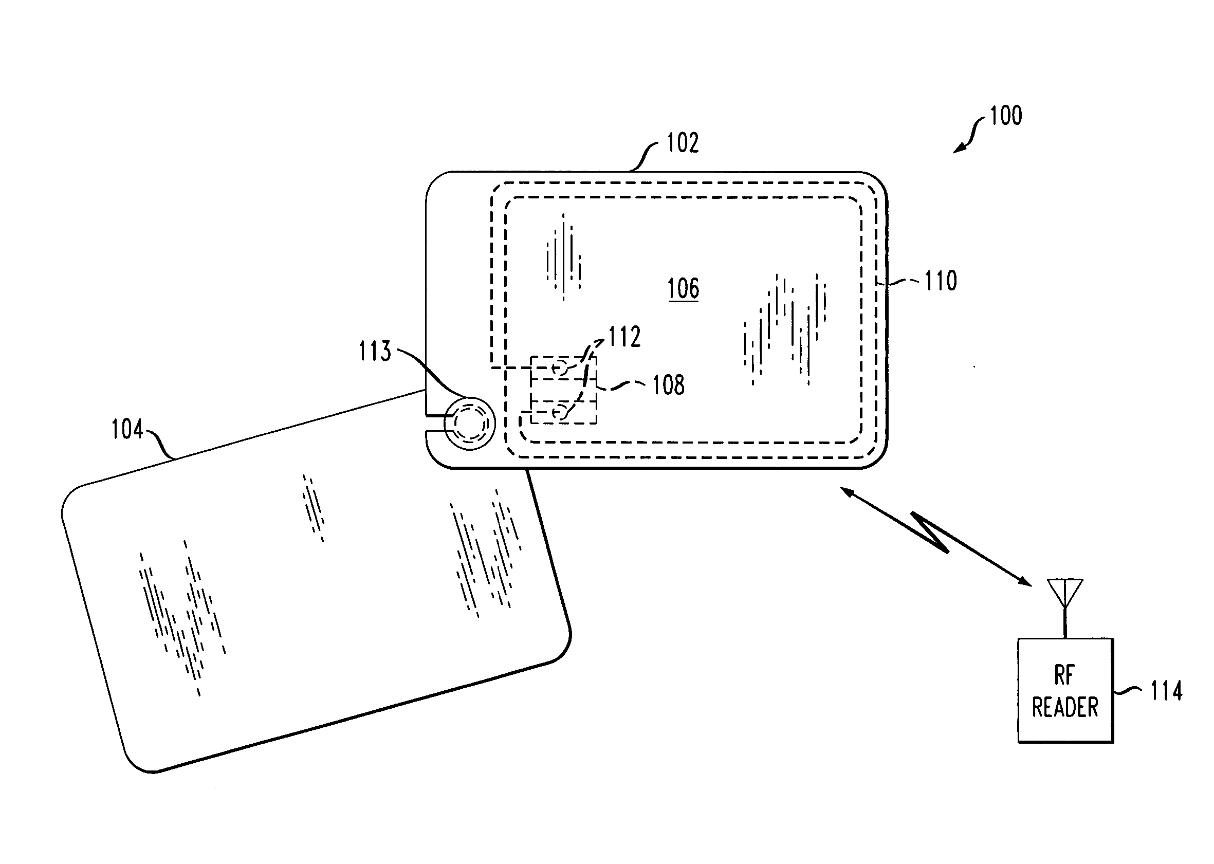
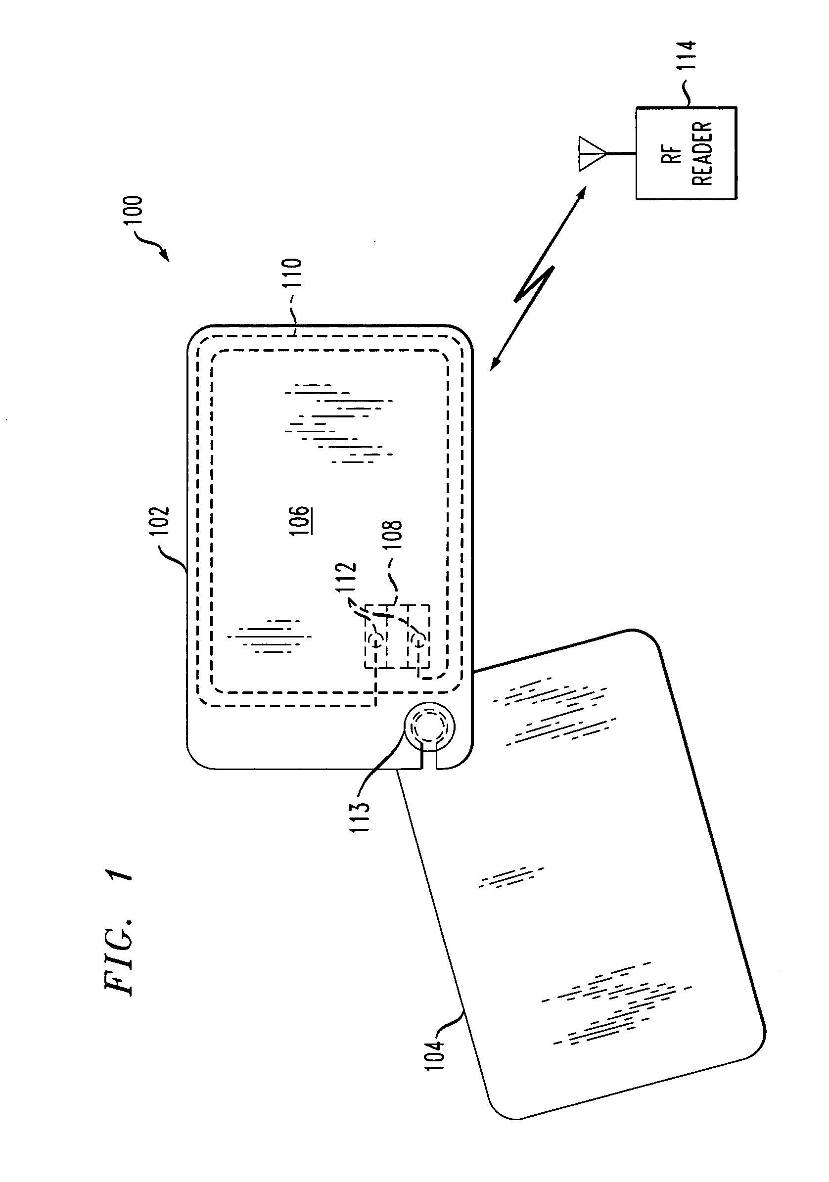
[0032] Attention should now be given to FIG. 1, which depicts an exemplary embodiment of a contactless proximity communications apparatus 100 in accordance with an aspect of the present invention. Apparatus 100 includes a body portion 102 and a signal-disrupting portion 104. Portion 102 in turn includes a body 106, a communications circuit 108 associated with the body, and an antenna 110 electrically coupled to the communications circuit 108. The communications circuit 108 can be any of a number of well-known RF integrated circuit chips. Antenna 110 can, as shown, include a number of windings located about the periphery of body 106 and electrically interconnected with appropriate contact regions 112 of circuit 108. While the present invention can be employed with any type of RF communications device (even powered devices, if desired), the exemplary embodiment shown in FIG. 1 envisions an inductively coupled device wherein the communications circuit 108 is in the form of a passive tr...


PUM


Abstract

Techniques for reducing or eliminating the likelihood of fraud in a contactless proximity communications apparatus are provided. The apparatus can include a body portion with a body, a communications circuit, and an antenna. The apparatus can also include a signal-disrupting portion that is mounted for motion, such as rotary or linear motion, with respect to the body portion and configured to substantially disrupt RF signals in a first position, and to move to a second position where RF communication is possible.

Description

CROSS-REFERENCE TO RELATED APPLICATION [0001] This patent application claims the benefit of U.S. Provisional Patent Application Ser. No. 60 / 708,686 filed on Aug. 16, 2005, and entitled “Contactless Proximity Communications Apparatus and Method.” The disclosure of the aforementioned Provisional Patent Application Ser. No. 60 / 708,686 is expressly incorporated herein by reference in its entirety.FIELD OF THE INVENTION [0002] The present invention generally relates to communications apparatus, and, more particularly, to a contactless proximity communications apparatus such as, for example, a contactless proximity payment card or other payment device. BACKGROUND OF THE INVENTION [0003] Contactless proximity communications apparatus, such as cards and other kinds of payment devices, are exposed to a number of threats that do not typically arise in connection with magnetic strip or contact-based devices or cards. In contactless proximity devices or cards, wireless transfer of data occurs w...

Claims


Application Information

Patent Timeline
Patent Type & Authority Applications(United States)
IPC IPC(8): G06K7/08G06K5/00G06K19/06
CPCG06K19/07327H04B5/02G06K5/00G06K19/06
Inventor KRANZLEY, ARTHURLULIC, MARKWANKMUELLER, JOHN
Owner MASTERCARD INT INC
Why Eureka
Try Eureka