Magnetic drive metering pump

a magnetic drive and metering pump technology, applied in the direction of electrical apparatus, dynamo-electric converter control, dynamo-electric machines, etc., can solve the problems of reducing the amount of metering, the inability of magnetic drive metering pumps to be used over a wide range of operating pressures with the desired accuracy, and the exacerbated errors of calibration

Active Publication Date: 2007-02-22
PROMINENT
View PDF6 Cites 147 Cited by
  • Summary
  • Abstract
  • Description
  • Claims
  • Application Information

AI Technical Summary

Problems solved by technology

The amount of the deformation is lost to the effective stroke motion and the result is that with increasing operational pressure, the metered amount reduces.
Thus, magnetic drive metering pumps normally cannot be used over a wide range of operating pressures with the desired accuracy; moreover, the errors which arise by calibration are exacerbated as they are included in further calculations.
However, said calibration measurement must be carried out in use under actual operating conditions and particularly when using aggressive chemicals, is a step which is extremely difficult.
Current magnetic drives have just a few simple parts and thus are easy to manufacture, but are relatively limited in application and suffer from disadvantages as regards the hydraulic properties of the metering process compared with a motor-driven pump.
The motor drive, which is transferred, for example by means of a gear or cam, has more applications and for many processes it has better metering properties, but is much more expensive to produce.

Method used


Image

  • Magnetic drive metering pump
  • Magnetic drive metering pump
  • Magnetic drive metering pump

Examples


Embodiment Construction

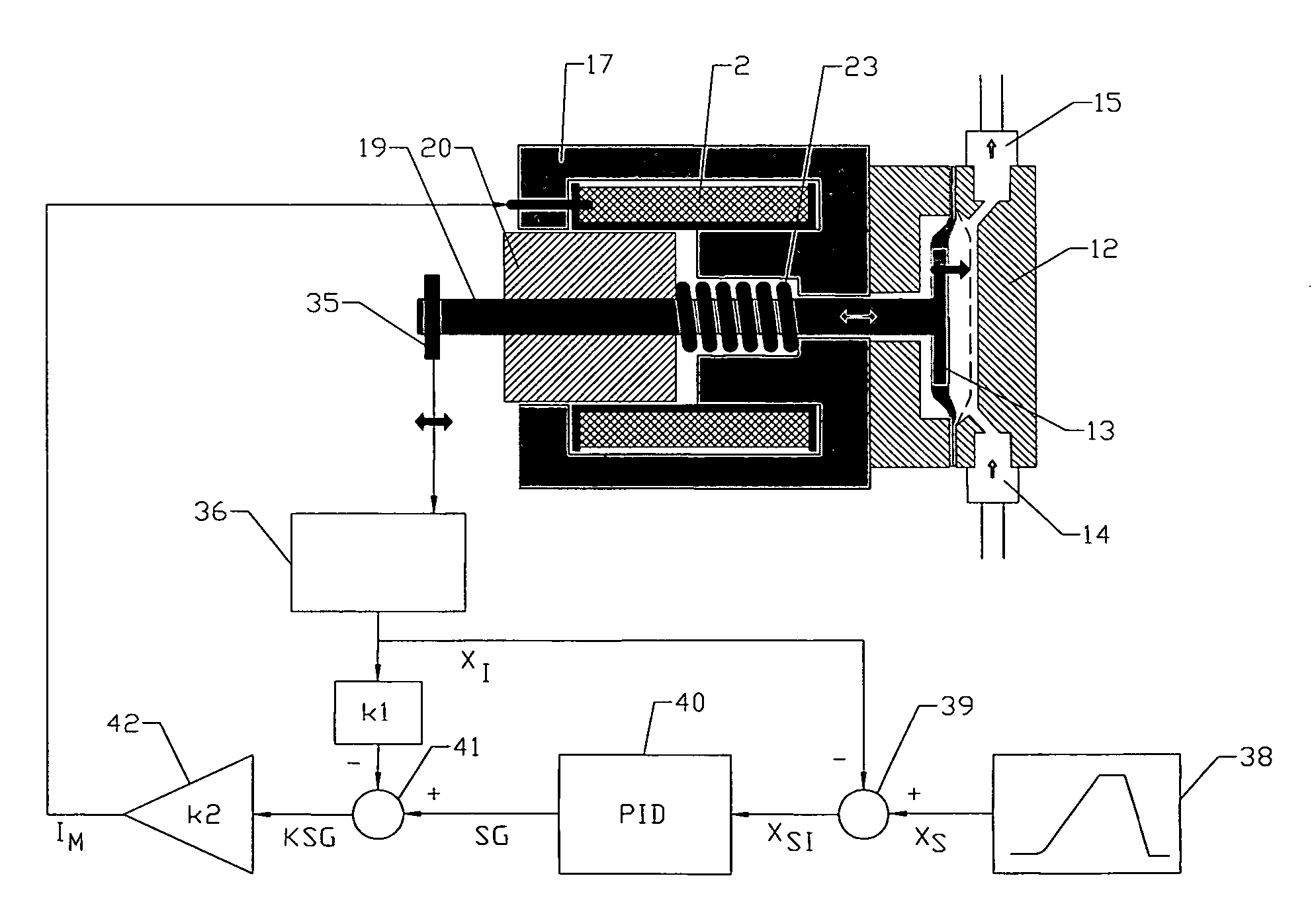
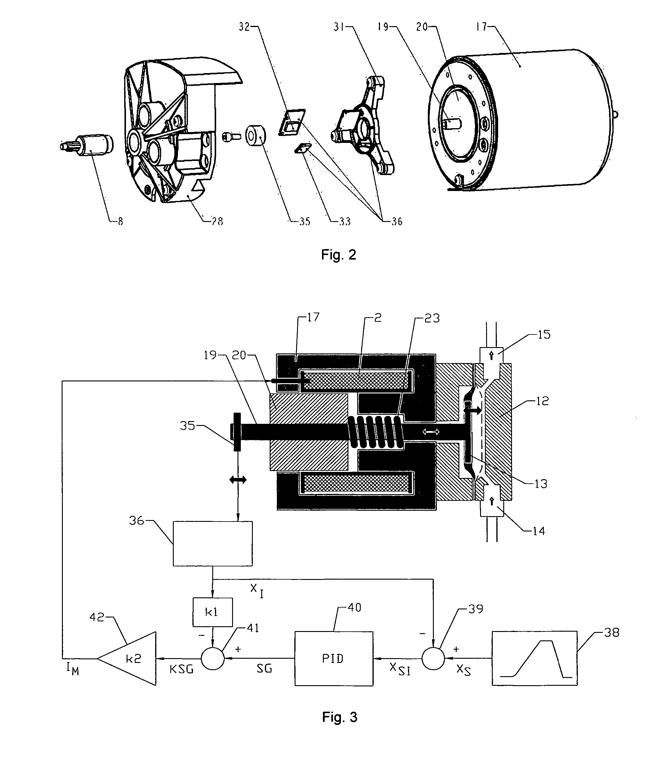
[0029] The particular aim of the invention is to overcome the known disadvantages as regards the hydraulic properties of the metering process and to provide a variable, larger operational range for magnetic drive metering pumps without negatively affecting its advantages, namely easy and cheap manufacture. Further, the motion of the thrust member and the associated connecting rod should be matched to the nominal details so that the metering process itself is adjustable, and any defects caused by manufacture or disadvantageous properties of the elastic diaphragm can be taken into account and compensated for by the control system. The positional indicator should be structured so that variations in assembly and / or problems which arise during service regarding the positional measurement can be compensated for by on-board electronics.

[0030] The problem is solved by dint of a reference element which is associated with the module constituted by the thrust member and connecting rod, the po...


PUM


Abstract

A magnetic drive metering pump in which a movable thrust member fixed to a connecting rod is axially movable in a longitudinal axis in a magnet shroud anchored in a pump housing so that the thrust member with the connecting rod, on electrically driving (actuating) the magnetizing coil, is drawn into the magnet shroud against the force of a recuperating spring, reducing an air gap between the thrust member and an inner face of magnetic shroud, into a bore in the magnet shroud and after deactivating the magnet the thrust member is returned to the starting position by the recuperating spring so that the thrust member and an elastic displacement member actuated thereby on carries out an oscillating motion continued activation and deactivation of the magnetizing coil, which diaphragm cooperates alternately with an outlet and an inlet valve to produce a pump stroke (pressure stroke) and a priming stroke in a metering head arranged in the longitudinal axis. In such a magnetic drive metering pump, a reference element is associated with the module constituted by the thrust member and connecting rod, the position of which reference element is detected by a positional sensor, wherein the positional sensor provides an actual signal which is in a fixed relationship to the position of the reference element, and in that the motion of the unit formed by the thrust member and the connecting rod is influenced as regards control accuracy via a control circuit so that it follows a predetermined nominal profile.

Description

BACKGROUND OF THE INVENTION [0001] The invention relates to a magnetic drive metering pump in which a movable thrust member fixed to a connecting rod is axially movable in a longitudinal axis in a magnet shroud anchored in a pump housing. A compression spring or recuperating spring, with uncontrolled magnets, keeps the thrust member from an inner face of the magnet shroud so that an airgap is formed between the two faces. The thrust member with the connecting rod, on electrically driving (actuating) the magnetizing coil, is drawn into the magnet shroud against the force of a recuperating spring, reducing the airgap, into a bore in the magnet shroud and after deactivating the magnet the thrust member is returned to the starting position by the recuperating spring so that the thrust member and an elastic displacement member actuated thereby carries out an oscillating motion on continued activation and deactivation of the magnetizing coil, which diaphragm cooperates alternately with an...

Claims


Application Information

Patent Timeline
Patent Type & Authority Applications(United States)
IPC IPC(8): H02K41/00H02K7/06
CPCF04B17/042F04B43/04F04B2201/0201F04B2201/0202
Inventor FREUDENBERGER, THOMASHOEHLER, ANDREAS
Owner PROMINENT
Why Eureka
Try Eureka