Rotary electric machine

Active Publication Date: 2007-02-22
SANYO DENKI CO LTD
View PDF15 Cites 7 Cited by
  • Summary
  • Abstract
  • Description
  • Claims
  • Application Information

AI Technical Summary

Benefits of technology

[0004] An object of the present invention is to provide a rotary electric machine, of which the occupied volume can be prevented from increasing and which allows for effective utilization of a space in an electric apparatus equipped with the rotary electric machine.
[0005] Another object of the present invention is to provide a rotary electric machine in which the insulation of respective connections between two or more lead-out wires of windings and two or more lead wires for external connections can be easily achieved.

Problems solved by technology

Therefore, a volume occupied by the rotary electric machine is increased, and accordingly, a space in electric apparatus equipped with the rotary electric machine cannot be utilized effectively.

Method used


Image

  • Rotary electric machine
  • Rotary electric machine
  • Rotary electric machine

Examples


Embodiment Construction

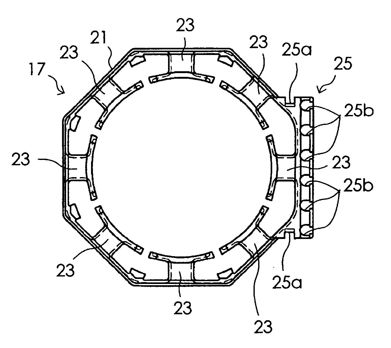
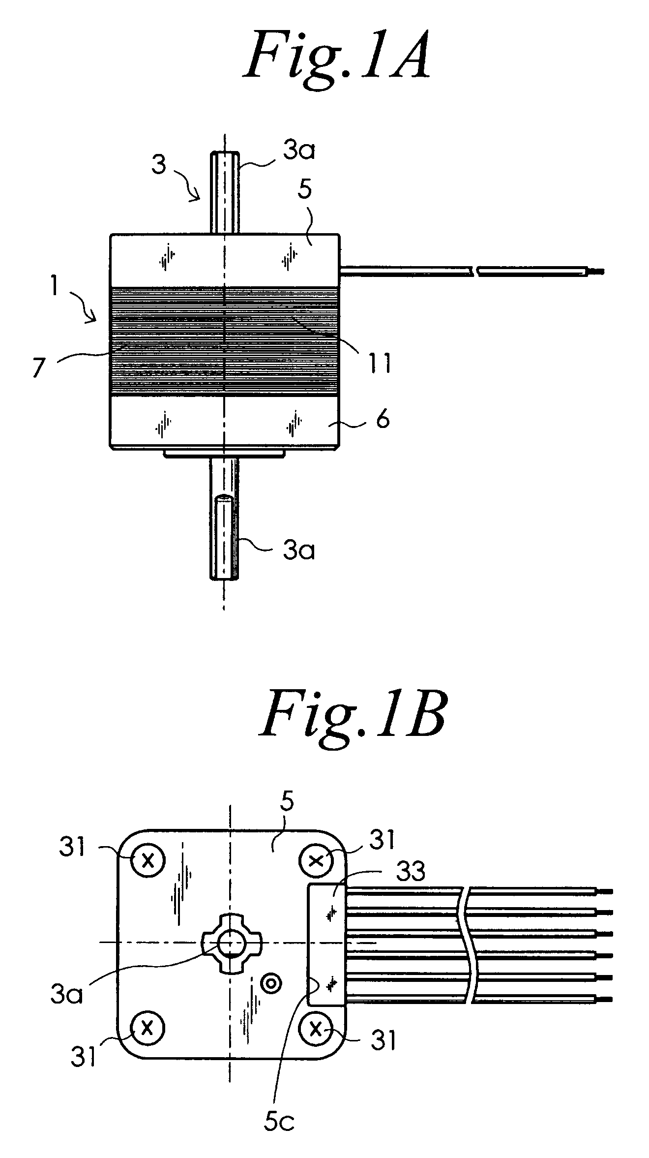
[0021] Hereinafter, an example of embodiment of the present invention will be described in detail with reference to the drawings. FIGS. 1A and 1B are respectively a front view and a plan view of a rotary electric machine according to an embodiment of the present invention. FIGS. 2A and 2B are respectively a front view and a plan view of a stator, t which lead wires are connected, of the rotary electric machine shown in FIGS. 1A and 1B. In short, FIGS. 2A and 2B respectively show the configuration in which a rotor 3 and a pair of end brackets 5, 6 are omitted from the rotary electric machine shown in FIGS. 1A and 1B. The rotary electric machine according to this embodiment comprises a stator 1, a rotor 3, a part of which is disposed inside the stator 1 and rotates therein, and a pair of end brackets 5 and 6 as shown in FIGS. 1A and 1B. The stator 1 includes a stator core 7 and eight windings 9 of one or more phases (in this embodiment, two phases) as shown in FIGS. 2A and 2B. The sta...


PUM


Abstract

The present invention provides a rotary electric machine, of which the occupied volume can be reduced and which allows a space in an electric apparatus equipped therewith to be utilized effectively. A slot insulator 15 is integrally formed with a holder mounting portion 25, a whole or major part of which is positioned on one of end faces of a yoke 11 of a stator core 7. A lead wire holder 27 includes a connection holding portion 27a for disposing a plurality of connections 30, in which lead-out wires of windings are connected with corresponding core wires 29a of lead wires 29, at a predetermined interval so that the connections do not contact with each other. The lead wire holder 27 is arranged so that the connection holding portion 27a is positioned over a part of the windings 9 and the holder mounting portion 25 when the lead wire holder is attached to the holder mounting portion 25. One end bracket, which faces to one of the end faces of the yoke, is formed with a recess which opens toward both sides in the axial direction thereof as well as opens outwardly in a radial direction of a shaft. The holder mounting portion 25 and lead wire holder 27 are received within the recess when the one end bracket is attached to the one end face of the yoke.

Description

FIELD OF THE INVENTION [0001] The present invention relates to a rotary electric machine, particularly to a rotary electric machine in which a plurality of lead-out wires of windings are respectively connected to a plurality of lead wires for external connections. BACKGROUND OF THE INVENTION [0002] Japanese Patent Application Laid-open Publication No. 2002-359944 discloses a rotary electric machine, which comprises a stator core, windings of one or more phases wound on the stator core, a slot insulator made of an insulating resin and mounted on the stator core, and a lead wire holding structure for holding two or more lead wires for external connections to which two or more lead-out wires of the windings are respectively connected. In this rotary electric machine, the lead wire holding structure includes a lead wire holder made of a synthetic resin for holding the lead wires with end portions of the lead wires being arranged at a predetermined interval, and a holder mounting portion...

Claims


Application Information

Patent Timeline
IPC IPC(8): H02K11/00
CPCH02K3/522
Inventor OOHASHI, MASAAKIMIYAIRI, SHIGENORITAKESHITA, IKUO
Owner SANYO DENKI CO LTD
Why Eureka
Try Eureka