Isolated converter with high boost ratio

a converter and boost technology, applied in the field of isolated converters, can solve the problems of lower conversion efficiency, higher stress on the switch and/or the diode, and lower circuit component costs, so as to increase the efficiency of the boost circuit, reduce the cost of the circuit component, and high boost ratio

Active Publication Date: 2021-08-10
DELTA ELECTRONICS INC
View PDF40 Cites 0 Cited by
  • Summary
  • Abstract
  • Description
  • Claims
  • Application Information

AI Technical Summary

Benefits of technology

[0011]Accordingly, the isolated converter with high boost ratio is provided to increase efficiency of the boost circuit, reduce circuit component costs, and reduce occupied volume due to the reduction of the number of coil turns of the isolated transformer.
[0014]Accordingly, the isolated converter with high boost ratio is provided to increase efficiency of the boost circuit, reduce circuit component costs, and reduce occupied volume due to the reduction of the number of coil turns of the isolated transformer.

Problems solved by technology

However, disadvantages of the multi-stage boost converters are higher circuit component costs and lower conversion efficiency.
If the voltage conversion ratio is too high, however, excessive number of the secondary-side coil turns causes an increase in the leakage inductance of the isolated transformer, resulting in higher stress on the switch and / or the diode, and therefore the components with higher rated voltage need to be used.
Further, the turned-on resistance of the switch becomes larger cause increased circuit costs, reduced efficiency, and larger transformer volume.
If the voltage conversion ratio is too high, however, excessive number of the coil turns causes the increased coil turns of the transformer, increased volume of the transformer, and reduced efficiency.
In order to implement the high boost ratio (voltage conversion ratio), however, the excessive number of the coil turns causes larger transformer volume, higher stress of the semiconductor switch, and lower conversion efficiency.

Method used


Image

  • Isolated converter with high boost ratio
  • Isolated converter with high boost ratio
  • Isolated converter with high boost ratio

Examples


first embodiment

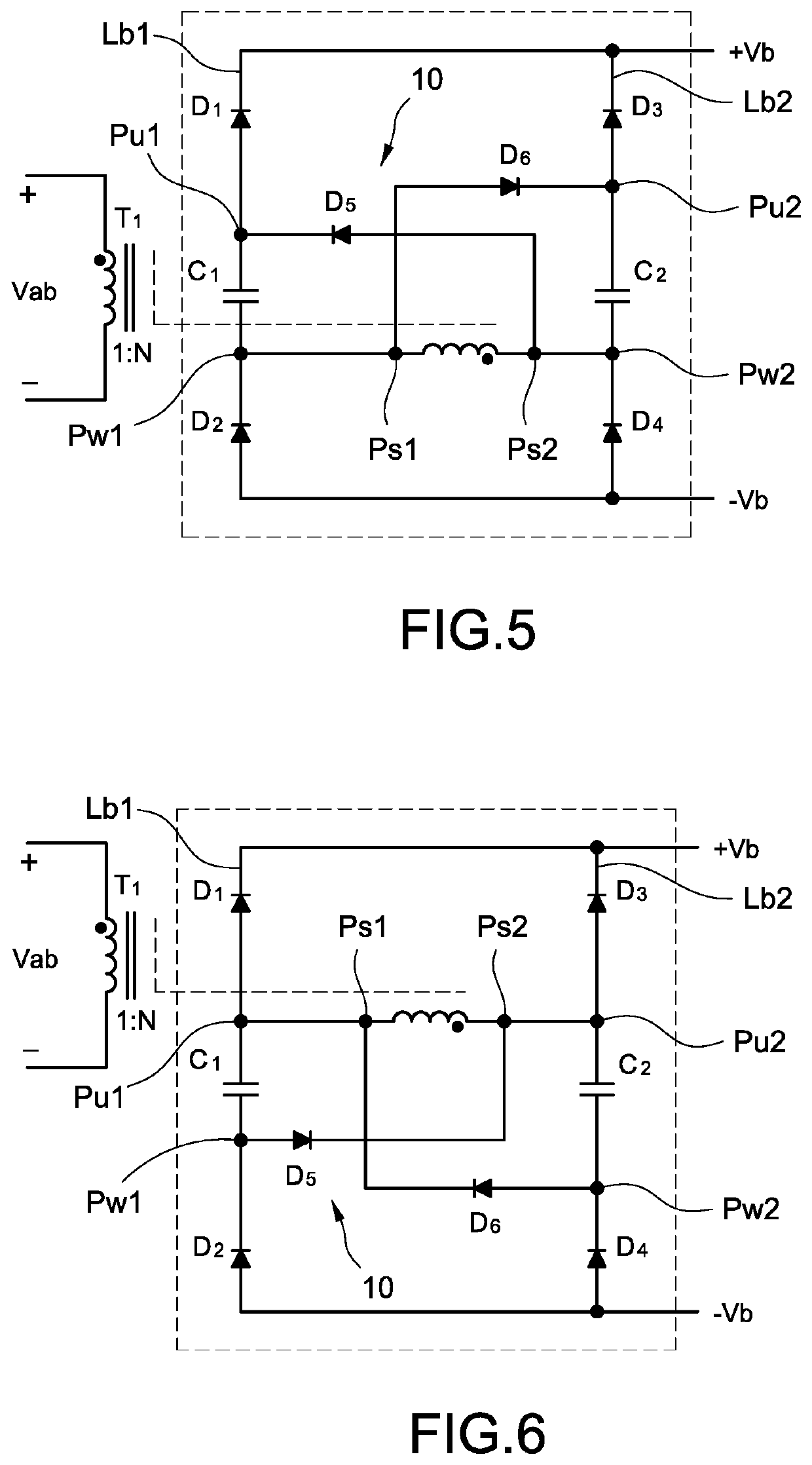
[0035]Please refer to FIG. 5, which shows a single-bus circuit structure of an isolated converter with high boost ratio according to the present disclosure. The isolated converter includes a transformer T1, a first bridge arm Lb1, a second bridge arm Lb2, and a boost circuit 10. The transformer T1 includes a secondary side having a secondary side first node Ps1 and a secondary side second node Ps2. The first bridge arm Lb1 includes a first diode D1 and a second diode D2. A cathode of the first diode D1 is coupled to a DC positive output node+Vb, an anode of the first diode D1 is coupled to a first bridge arm upper node Pu1, an anode of the second diode D2 is coupled to a DC negative output node −Vb, and a cathode of the second diode D2 is coupled to a first bridge arm lower node Pw1. The second bridge arm Lb2 includes a third diode D3 and a fourth diode D4. A cathode of the third diode D3 is coupled to the DC positive output node+Vb, an anode of the third diode D3 is coupled to a se...

third embodiment

[0043]Please refer to FIG. 9, which shows a single-bus circuit structure of the isolated converter with high boost ratio according to the present disclosure, and the circuit structure of FIG. 9 is a combination of the circuit structure of FIG. 5 and the circuit structure of FIG. 6. As shown in FIG. 9, the number of the at least two capacitors is four, including a first capacitor C1, a second capacitor C2, a third capacitor C3, and a fourth capacitor C4. The number of the at least one fifth diode D5 is two, including an upper fifth diode D5 and a lower fifth diode D5. The number of the at least one sixth diode D6 is two, including an upper sixth diode D6 and a lower sixth diode D6.

[0044]Two ends of the first capacitor C1 are coupled to the secondary side first node Ps1 and the first bridge arm upper node Pu1. Two ends of the second capacitor C2 are coupled to the secondary side second node Ps2 and the second bridge arm upper node Pu2. Two ends of the third capacitor C3 are coupled to...

fourth embodiment

[0047]Please refer to FIG. 10, which shows a single-bus circuit structure of the isolated converter with high boost ratio according to the present disclosure. The main difference between FIG. 10 and FIG. 9 is that all the diodes D1-D6 in FIG. 9 are replaced by power switches S1-S6. In this embodiment, the power switches S1-S6 are, for example but not limited to, metal-oxide-semiconductor field-effect transistors (MOSFETs). By actively controlling the power switches S1-S6, the isolated converter can achieve the function of bidirectional operation. Similarly, the diodes in the isolated converters shown in FIG. 5, FIG. 6, and FIG. 9 also can be replaced by power switches so that the isolated converter can achieve the function of bidirectional operation and achieve less conduction loss. In FIG. 5, FIG. 6, and FIG. 9, the “diode” is not limited to a diode that is independently packaged, it can be also a parasitic element of the power switch, such as a body diode of the MOSFET.

[0048]Pleas...


PUM


Abstract

An isolated converter with high boost ration includes a transformer, a first bridge arm, a second bridge arm, and a boost circuit. The transformer includes a secondary side having a secondary side first node and a secondary side second node. The first bridge arm includes a first diode and a second diode. The second bridge arm includes a third diode and a fourth diode. The boost circuit includes at least one fifth diode coupled between the first bridge arm and the secondary side second node, at least one sixth diode coupled between the second bridge arm and the secondary side first node, and at least two capacitors coupled to the secondary side first node and the secondary side second node.

Description

CROSS-REFERENCE TO RELATED APPLICATION[0001]This patent application claims the benefit of U.S. Provisional Patent Application No. 62 / 860,650, filed Jun. 12, 2019, and claims priority to CN202010248753.X filed Apr. 1, 2020. The entire disclosures of the above applications are all incorporated herein by reference.BACKGROUNDTechnical Field[0002]The present disclosure relates to an isolated converter, and more particularly to an isolated converter with high boost ratio.Description of Related Art[0003]The statements in this section merely provide background information related to the present disclosure and do not necessarily constitute prior art.[0004]Please refer to FIG. 1, which shows a circuit block diagram of a conventional non-isolated boost converter. If a high voltage conversion ratio (boost ratio) is required, for example more than 10 times, two or more than two boost (DC-to-DC) converters are used to implement the requirement of high boost ratio. As shown in FIG. 1, a first DC b...

Claims


Application Information

Patent Timeline
Patent Type & Authority Patents(United States)
IPC IPC(8): H02M3/335
CPCH02M3/33592H02M3/33553H02M3/33584H02M3/3353H02M3/26H02M3/07H02M3/3376Y02B70/10H02M1/0058
Inventor LIN, HUNG-CHIEHKAO, CHAO-LIHSIEH, YI-PINGHUANG, JIN-ZHONGKUO, CHAO-LUNGHUANG, HUNG-YULI, CHIH-HSIEN
Owner DELTA ELECTRONICS INC
Why Eureka
Try Eureka