
System and method for monitoring an optical communication system

a technology of optical communication system and optical path, applied in electromagnetic repeaters, instruments, electromagnetic transmission, etc., can solve the problem that hllb monitoring generally does not allow monitoring of elements in optical path between coupling points

Active Publication Date: 2007-02-22
SUBCOM LLC
View PDF12 Cites 45 Cited by
  • Summary
  • Abstract
  • Description
  • Claims
  • Application Information

AI Technical Summary

Problems solved by technology

Unlike OTDR / COTDR monitoring methods, HLLB monitoring generally does not allow monitoring of elements in the optical path between coupling points, except inasmuch as those elements affect the loop gain measured for each coupling point.

Method used


Image

  • System and method for monitoring an optical communication system
  • System and method for monitoring an optical communication system
  • System and method for monitoring an optical communication system

Examples


Embodiment Construction

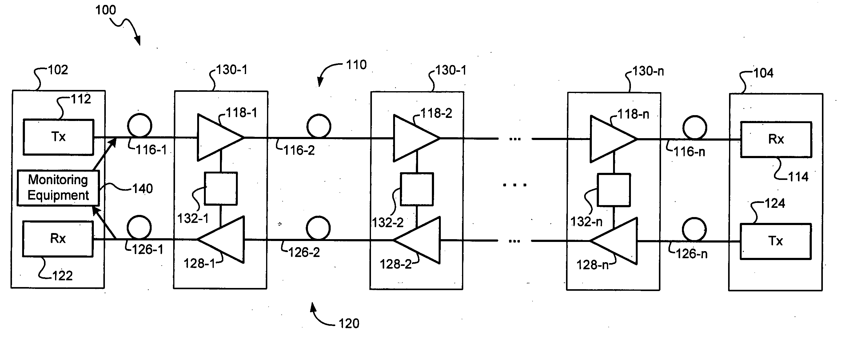
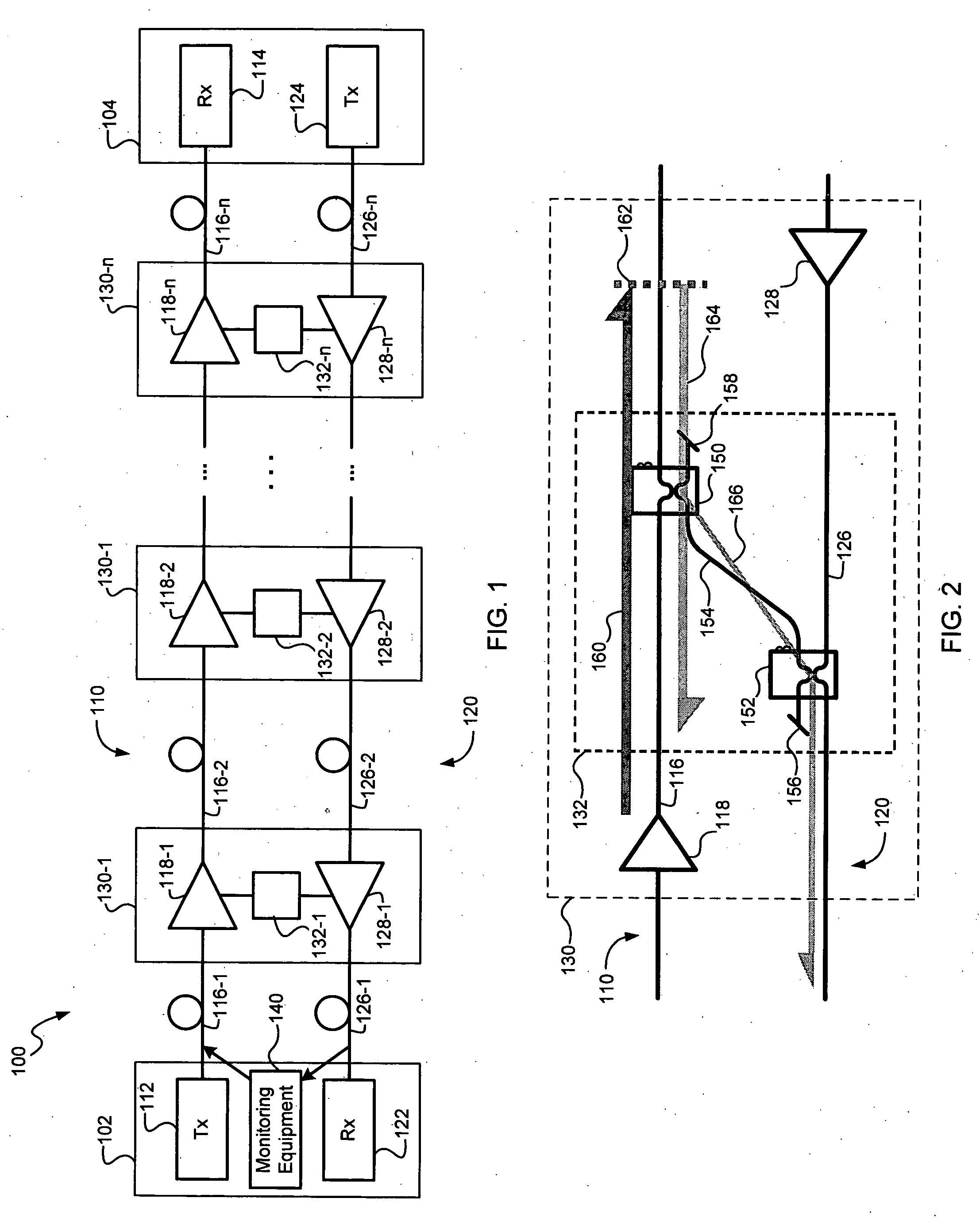
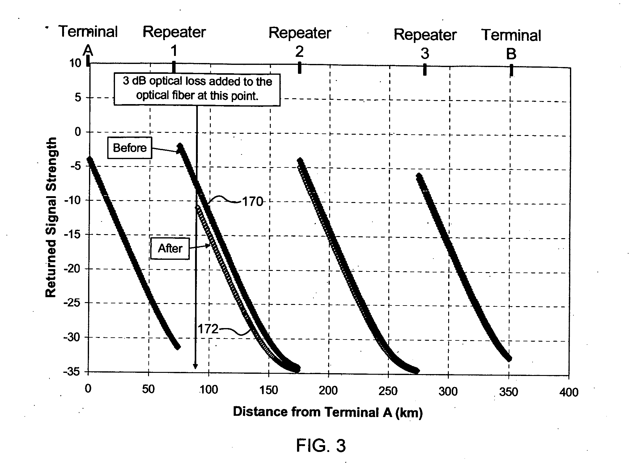
[0026] A monitoring system and method, consistent with the present invention, may be used to monitor one or more optical paths in an optical communication system. Consistent with one embodiment, the monitoring system and method may be used to derive loop gain data sets from optical 'time domain reflectometry (OTDR) or coherent optical time domain reflectometry (COTDR) data. Consistent with another embodiment, the monitoring system and method may also use differential monitoring techniques to obtain data representing gain tilt in the optical communication system, which may be used to locate an anomalous loss or gain in the optical communication system. Differential monitoring techniques may be used with OTDR, COTDR and / or high loss loop back (HLLB) monitoring, as described in greater detail below. The monitoring system and method may be used during system assembly or after a system has been installed to provide either in-service or out-of-service testing.

[0027] Referring to FIG. 1, ...


PUM

PropertyMeasurementUnit
distanceaaaaaaaaaa
distanceaaaaaaaaaa
distanceaaaaaaaaaa

Abstract

A monitoring system and method may be used to monitor an optical communication system. A monitoring system and method may be used to derive loop gain data sets from optical time domain reflectometry (OTDR) or coherent optical time domain reflectometry (COTDR) data. A monitoring system and method may also use differential monitoring techniques to obtain data representing gain tilt in the transmission system and to locate an anomalous loss or gain in the transmission system.

Description

TECHNICAL FIELD [0001] The present invention relates to monitoring optical communications systems and more particularly, to a system and method for monitoring an optical path in an optical communications system by monitoring features of the gain-versus-wavelength characteristics in the optical path. BACKGROUND INFORMATION [0002] Bi-directional optical communications systems may be built from pairs of optical paths connecting terminating points (e.g., terminals) of the system. Each optical path may transmit information encoded on an optical carrier from one terminal to the other terminal. In a long haul optical communication system, each optical path may be built from a sequence of concatenated spans. Each of the spans may include a medium for transmitting the optical signal (e.g., one or more optical fibers) and an amplifier (e.g., an optical amplifier) to compensate in whole or in part for optical loss resulting from propagation through the optical medium. An optical communication ...

Claims


Application Information

Patent Timeline
Patent Type & Authority Applications(United States)
IPC IPC(8): G01N21/00H04B10/29
CPCH04B10/071
Inventor ABBOTT, STUART M.
Owner SUBCOM LLC
Learn More