Darkfield illumination system

a technology of illumination system and concave mirror, which is applied in the field of darkfield illumination system, can solve the problems that the construction of concave mirror as a segmented mirror is difficult to achieve with the required accuracy, and achieve the effect of high uniformity

Inactive Publication Date: 2007-02-22
CARL ZEISS JENA GMBH
View PDF9 Cites 13 Cited by
  • Summary
  • Abstract
  • Description
  • Claims
  • Application Information

AI Technical Summary

Benefits of technology

The invention uses individual mirror segments to create an annular mirror that faces the light source. This results in a highly uniform distribution of both sagittal and meridional rays across the object field. The object-side annular mirror is designed as an aspherical mirror, which helps to achieve this uniformity.

Problems solved by technology

The technical problem addressed in this patent text relates to how to achieve effective darkfield illumination in optical light microscopes at higher magnitudes without compromising on light efficiency or requiring expensive and complex equipment. Existing solutions like annular diaphargams, planar mirror arrangements, and other methods mentioned above all have limitations when it comes to achieving large field illumination while maintaining good image quality.

Method used


Image

  • Darkfield illumination system
  • Darkfield illumination system
  • Darkfield illumination system

Examples


Embodiment Construction

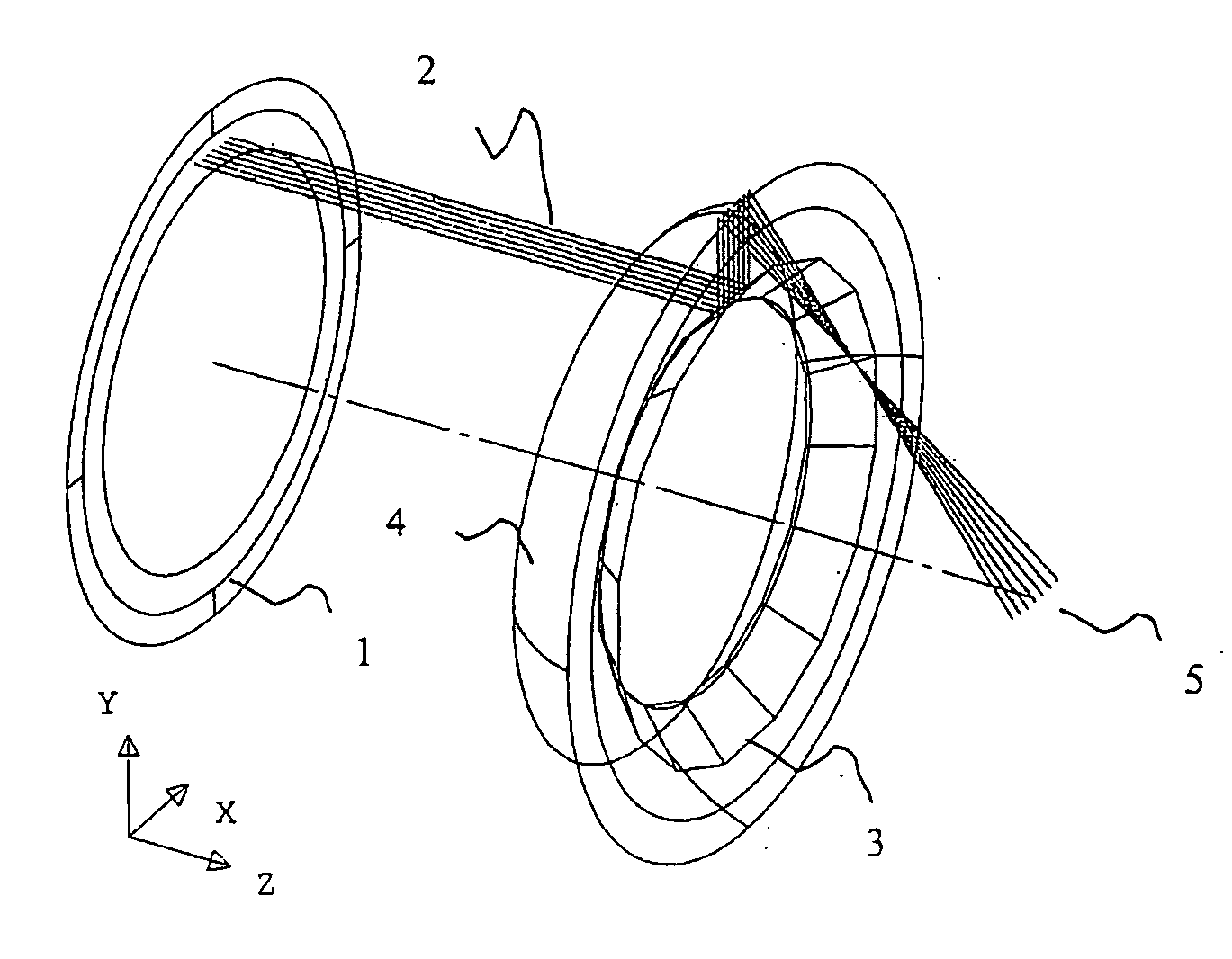
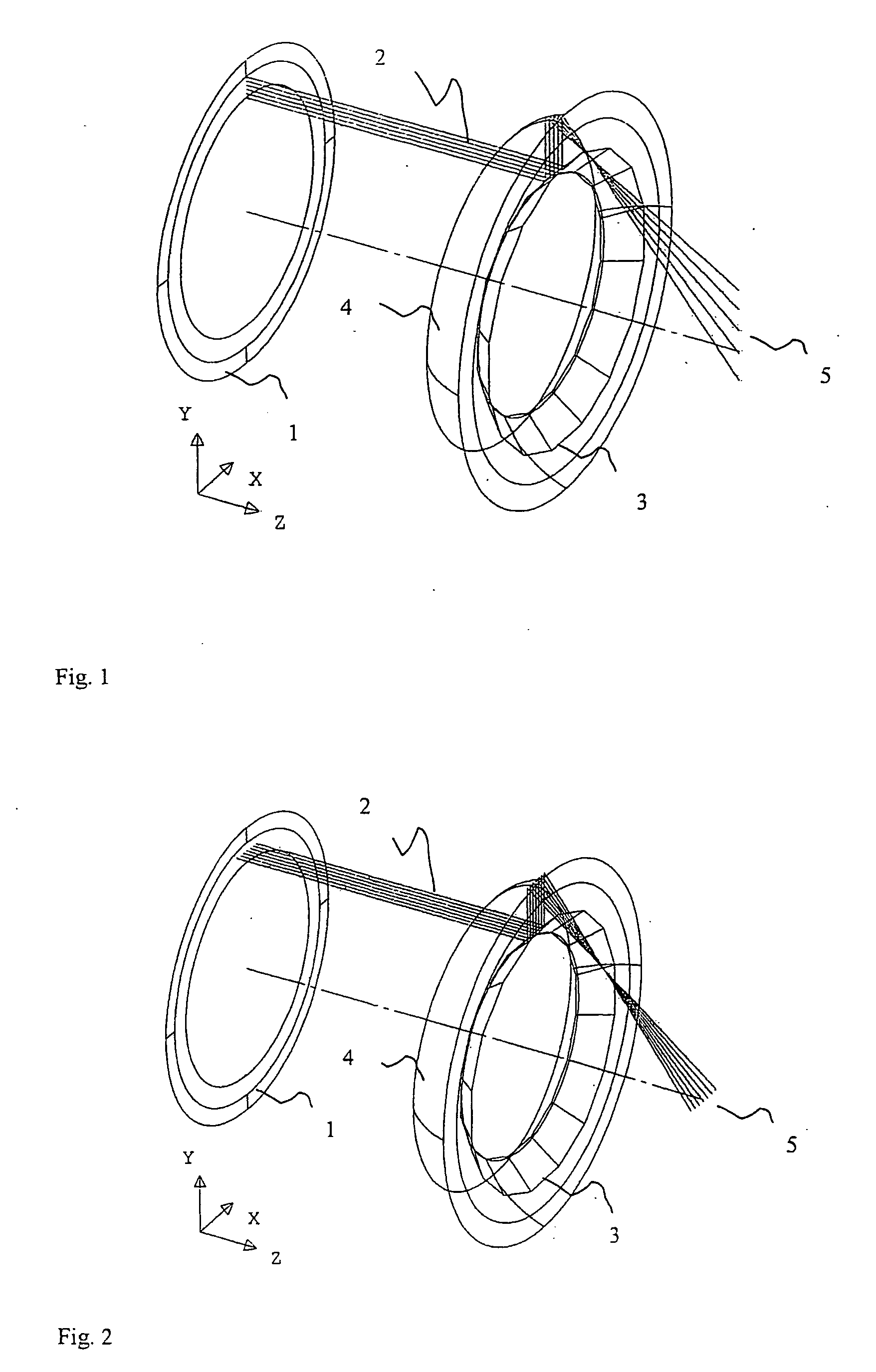
[0028]FIG. 1 shows a three-dimensional view of a darkfield illumination system according to the invention. The meridional rays 2 coming from the light source 1, shown schematically, are reflected at the segment mirror 3 outwardly on the aspherical mirror 4. The latter focuses the rays on a point between the mirror and the object. The light rays are subsequently scattered again uniformly over the entire object field 5.

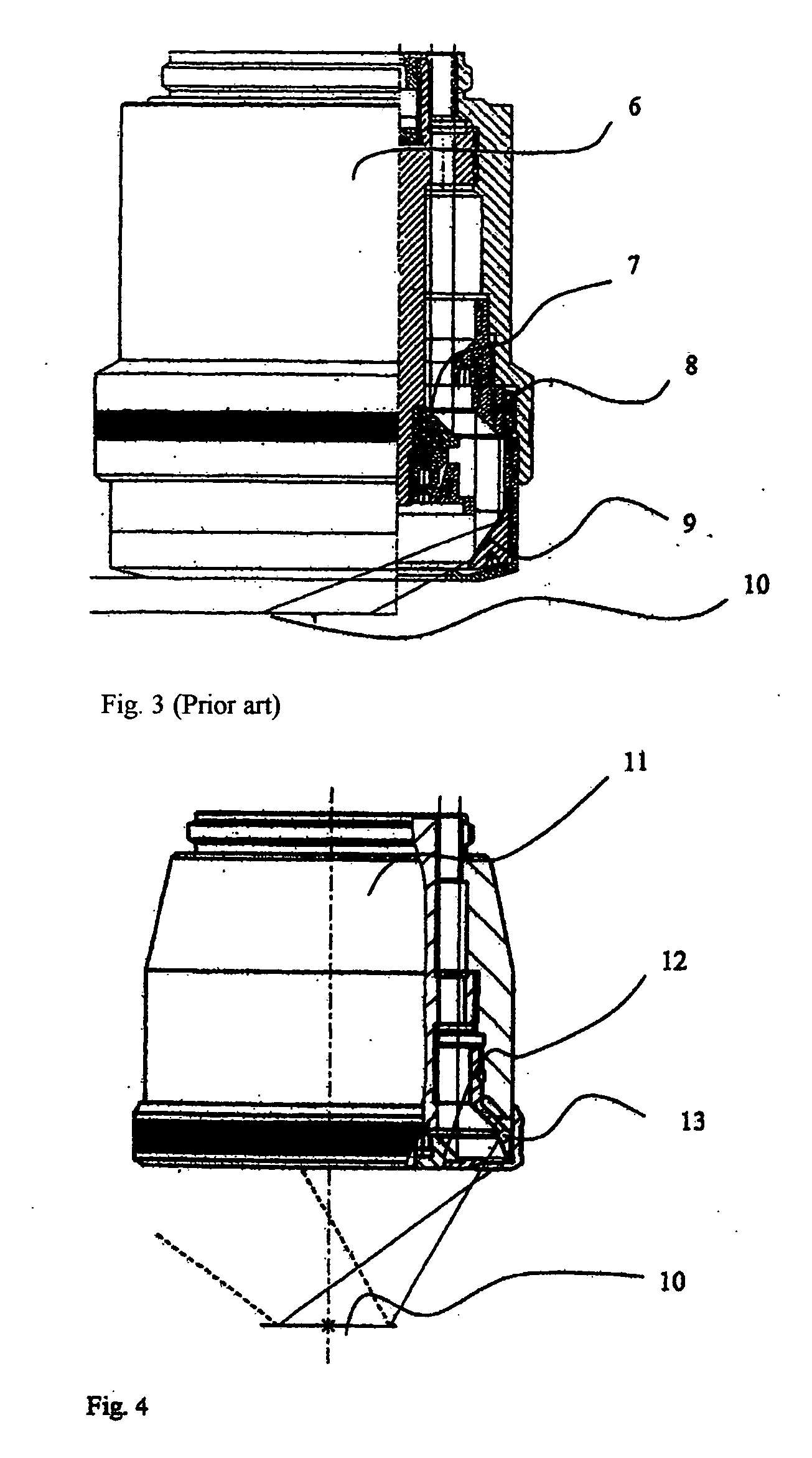
[0029] A uniform illumination is likewise achieved with the sagittal rays shown in FIG. 2 (identical reference numbers are used for identical elements). The known solution shown in FIG. 3 for a 2.5× objective 6 has a darkfield illumination channel with three reflections at truncated-cone mirrors 7, 8 and 9. The light reflected by the mirror 9 illuminates the object field 10, wherein only small working distances can be achieved based on the principle.

[0030]FIG. 4 shows the realization of the invention in a novel 2.5× objective 11. The darkfield illumination channel has...


PUM


Abstract

The invention is directed to a darkfield illumination system and is applicable in transmitted light microscopy and in incident light microscopy. A combination with a first, segmented mirror and a second, aspherical mirror is proposed for the purpose of uniform illumination of the large object fields occurring at low magnifications.

Description


Claims


Application Information

Patent Timeline
Owner CARL ZEISS JENA GMBH
Why Eureka
Try Eureka