Method of forming an interconnect structure for a semiconductor device

a technology of interconnect structure and semiconductor device, which is applied in the direction of semiconductor devices, semiconductor/solid-state device details, electrical apparatus, etc., can solve the problems of reducing the performance and density of modern very-large-scale integrated circuits, requiring complex interconnects, and affecting the reliability and performance of fabricated integrated circuits. achieve the effect of increasing contact adhesion, enhancing bonding yield, and increasing thermal conductivity

Inactive Publication Date: 2007-02-22
MICRON TECH INC
View PDF26 Cites 22 Cited by
  • Summary
  • Abstract
  • Description
  • Claims
  • Application Information

AI Technical Summary

Benefits of technology

[0012] The present invention provides a copper interconnect structure comprising an AlN barrier layer, which provides enhanced thermal conductivity. The present invention also provides for the passivation of copper surfaces by employing an AlN barrier layer on the copper that further enhances the bonding yield by increasing the contact adhesion between the metal layer and the bonding structure.

Problems solved by technology

The integration of a large number of components on a single IC chip requires complex interconnects.
Because of their increasing importance, the qualities of the interconnect structures drastically affect the reliability and performance of fabricated integrated circuits.
Currently, the interconnect structures are increasingly defining the limits in performance and density of modern very-large scale integrated (VLSI) circuits.
Unfortunately, however, as VLSI dimensions reach into the deep-submicron regime, aluminum and its alloys become limiting factors in achieving superior performance.
For example, with decreasing dimensions, the design rules become restricted by aluminum reliability concerns such as electromigration, which in turn increases the potential for open circuits or voids, stress-induced void formation, hillocks at relatively low temperatures, or humidity-induced corrosion.
Unfortunately, copper diffuses rapidly through SiO2 or other interlayer dielectrics, such as polyimides and parylenes.
Copper diffusion in the interconnect structure can destroy active devices, such as transistors or capacitors, formed in the IC substrate.
In addition, the adhesion of copper to interlayer dielectrics, particularly to SiO2, is generally poor and metal adhesion to the underlying substrate materials must be excellent to form reliable interconnect structures.
Further, copper oxidizes easily at low temperatures and has poor adhesion to substrates.
Many of these materials, however, also form nonconductive oxides, or have poor electrical or thermal conductivity, or a high thermal expansion.
Further, many of these barrier layers exhibit instability at temperatures higher than 500° C. Since a silicon substrate is generally subjected to subsequent steps during the IC fabrication, such as annealing or reflow processes which require temperatures higher than 500° C., there is a need for a barrier layer that is stable at the high temperatures required for subsequent substrate processes steps.
While copper diffusion and oxidation remain highly significant, high density integration in the microelectronics industry also faces the problem of large amount of heat generated as a result of controlling a large quantity of current.
Nevertheless, a major drawback of the thermal radiating substrates used in conventional power semiconductor devices is their extremely complicated construction.

Method used


Image

  • Method of forming an interconnect structure for a semiconductor device
  • Method of forming an interconnect structure for a semiconductor device
  • Method of forming an interconnect structure for a semiconductor device

Examples


Embodiment Construction

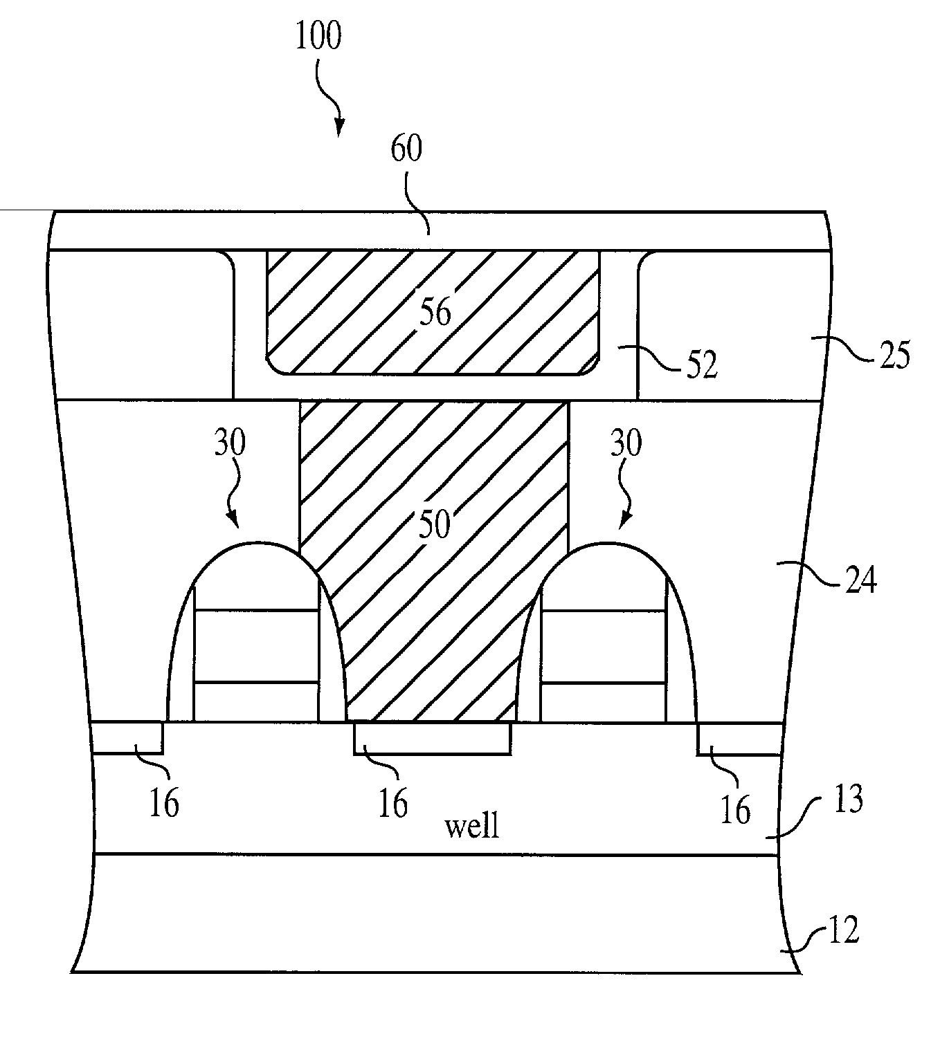
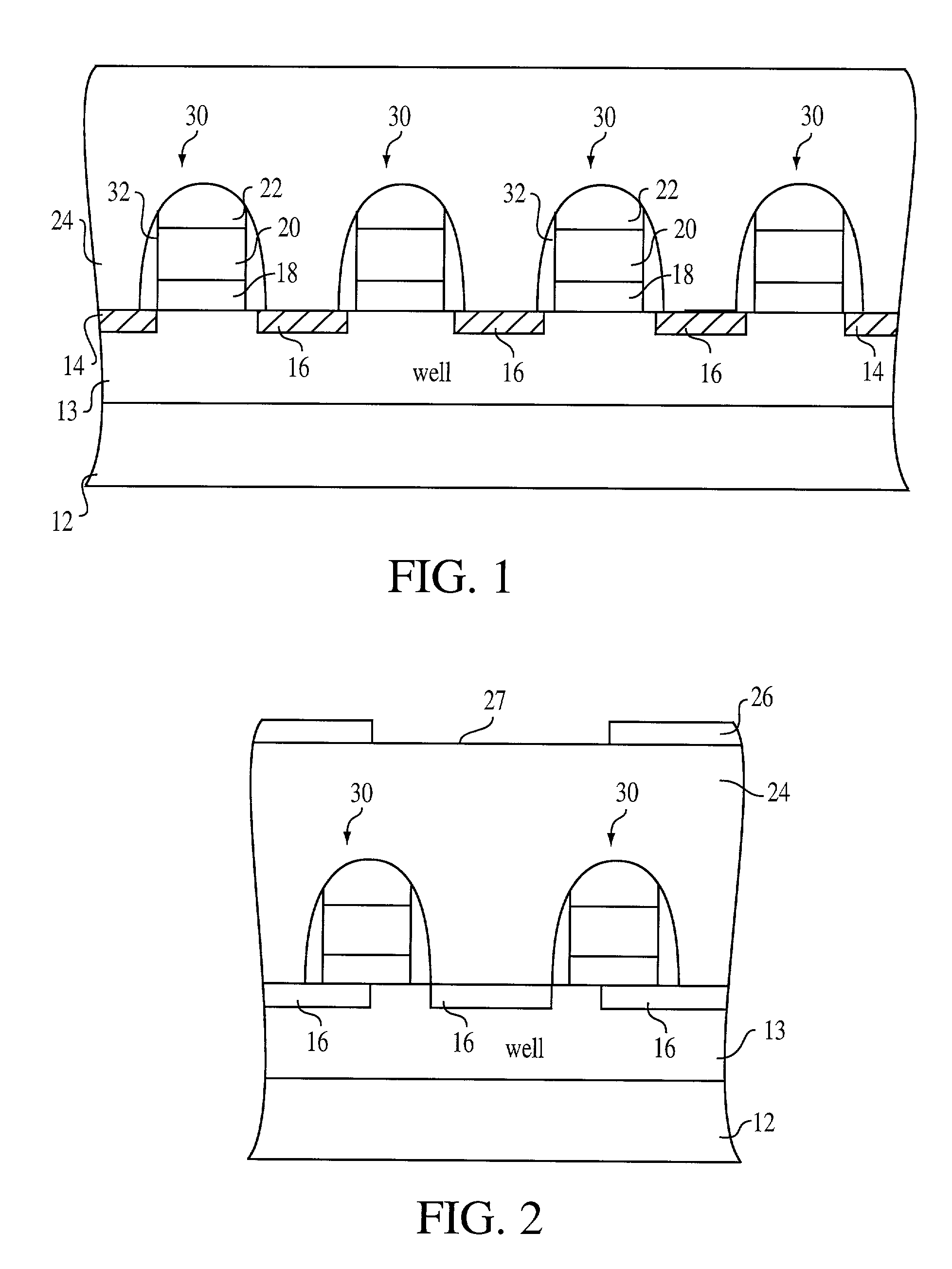
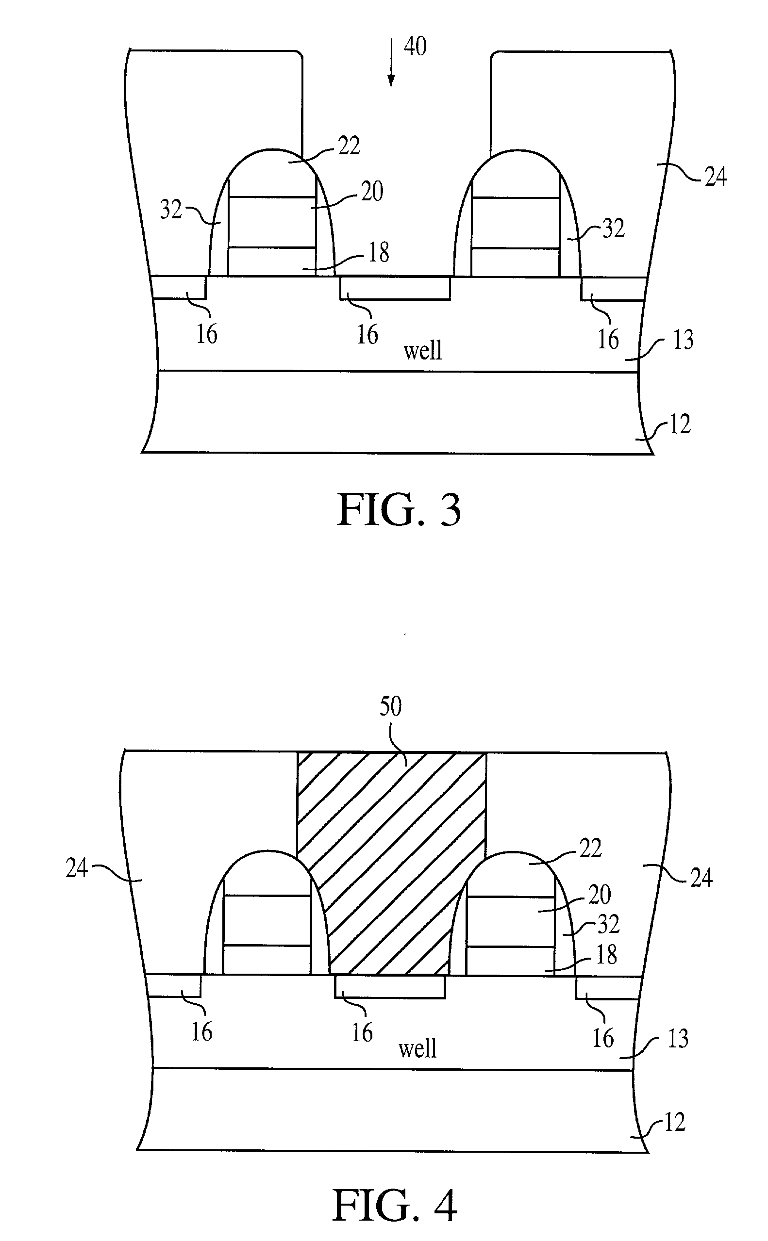
[0025] In the following detailed description, reference is made to various specific embodiments in which the invention may be practiced. These embodiments are described with sufficient detail to enable those skilled in the art to practice the invention, and it is to be understood that other embodiments may be employed, and that structural, electrical and methodology changes may be made and equivalents substituted without departing from the invention. Accordingly, the following detailed description is not to be taken in a limiting sense and the scope of the present invention is defined by the appended claims.

[0026] The term “substrate” used in the following description includes any semiconductor-based structure having an exposed silicon surface in which to form the structure of this invention. The term substrate is to be understood as including silicon-on-insulator, doped and undoped silicon, epitaxial layers of silicon supported by a base semiconductor foundation, and other semicon...


PUM

PropertyMeasurementUnit
temperaturesaaaaaaaaaa
thermal conductivityaaaaaaaaaa
dielectric strengthaaaaaaaaaa

Abstract

A copper interconnect structure is disclosed as comprising a copper layer and an aluminum nitride layer formed over the copper layer. The aluminum nitride layer passivates the copper layer surface and enhances the thermal conductivity of a semiconductor substrate by radiating heat from the substrate as well as from the copper layer.

Description

FIELD OF THE INVENTION [0001] The present invention relates to the field of interconnect structures for integrated circuit packages, and in particular, to the use of aluminum nitride (AlN) as a passivation layer for copper interconnect structures for electrically connecting two or more electronic components. BACKGROUND OF THE INVENTION [0002] The integration of a large number of components on a single IC chip requires complex interconnects. Ideally, the interconnect structures should be fabricated with minimal signal delay and optimal packing density. Because of their increasing importance, the qualities of the interconnect structures drastically affect the reliability and performance of fabricated integrated circuits. Currently, the interconnect structures are increasingly defining the limits in performance and density of modern very-large scale integrated (VLSI) circuits. [0003] Until recently, aluminum and its alloys have been widely used as conductive materials for electrical in...

Claims


Application Information

Patent Timeline
Patent Type & Authority Applications(United States)
IPC IPC(8): H01L21/44H01L21/4763H01L21/318H01L23/522H01L21/3205H01L21/768H01L23/367H01L23/52H01L23/532
CPCH01L21/76834H01L21/76843H01L21/76897H01L23/3677H01L23/53228H01L23/53238H01L2924/0002H01L23/5329H01L23/53295H01L2924/00H01L21/3205
Inventor MCTEER, ALLEN
Owner MICRON TECH INC
Why Eureka
Try Eureka