Traveling apparatus and traveling stopping method

a technology of traveling apparatus and stopping method, which is applied in the direction of transportation and packaging, remote control toys, cycles, etc., can solve the problem that the simple direction of traveling cannot be stopped easily

Inactive Publication Date: 2007-02-22
SONY CORP
View PDF4 Cites 12 Cited by
  • Summary
  • Abstract
  • Description
  • Claims
  • Application Information

AI Technical Summary

Benefits of technology

[0010] Consequently, with the traveling apparatus, the inertial force in the straightforwardly traveling direction generated on the housing by the traveling in the straightforwardly traveling direction can be almost canceled, and in this state, the driving rotation of the first and second wheels is stopped. As a result, such a situation that the housing is caused to roll to the straightforwardly traveling direction side by the inertial force in the straightforwardly traveling direction can be prevented almost with certainty. Consequently, traveling of the traveling apparatus and the traveling stopping method in the straightforwardly traveling direction can be stopped readily.

Problems solved by technology

Thus, the coaxial two-wheeled vehicle in the past has a problem that traveling in its straightforward direction cannot be stopped readily.

Method used


Image

  • Traveling apparatus and traveling stopping method
  • Traveling apparatus and traveling stopping method
  • Traveling apparatus and traveling stopping method

Examples


Embodiment Construction

[0027] Referring to the drawings, an embodiment of the present invention is described in detail hereinafter.

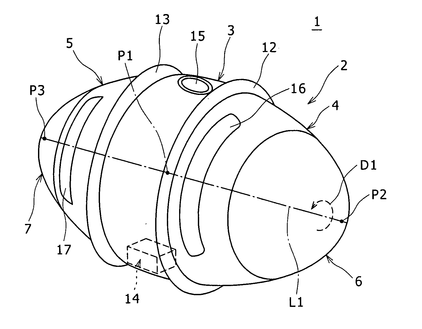
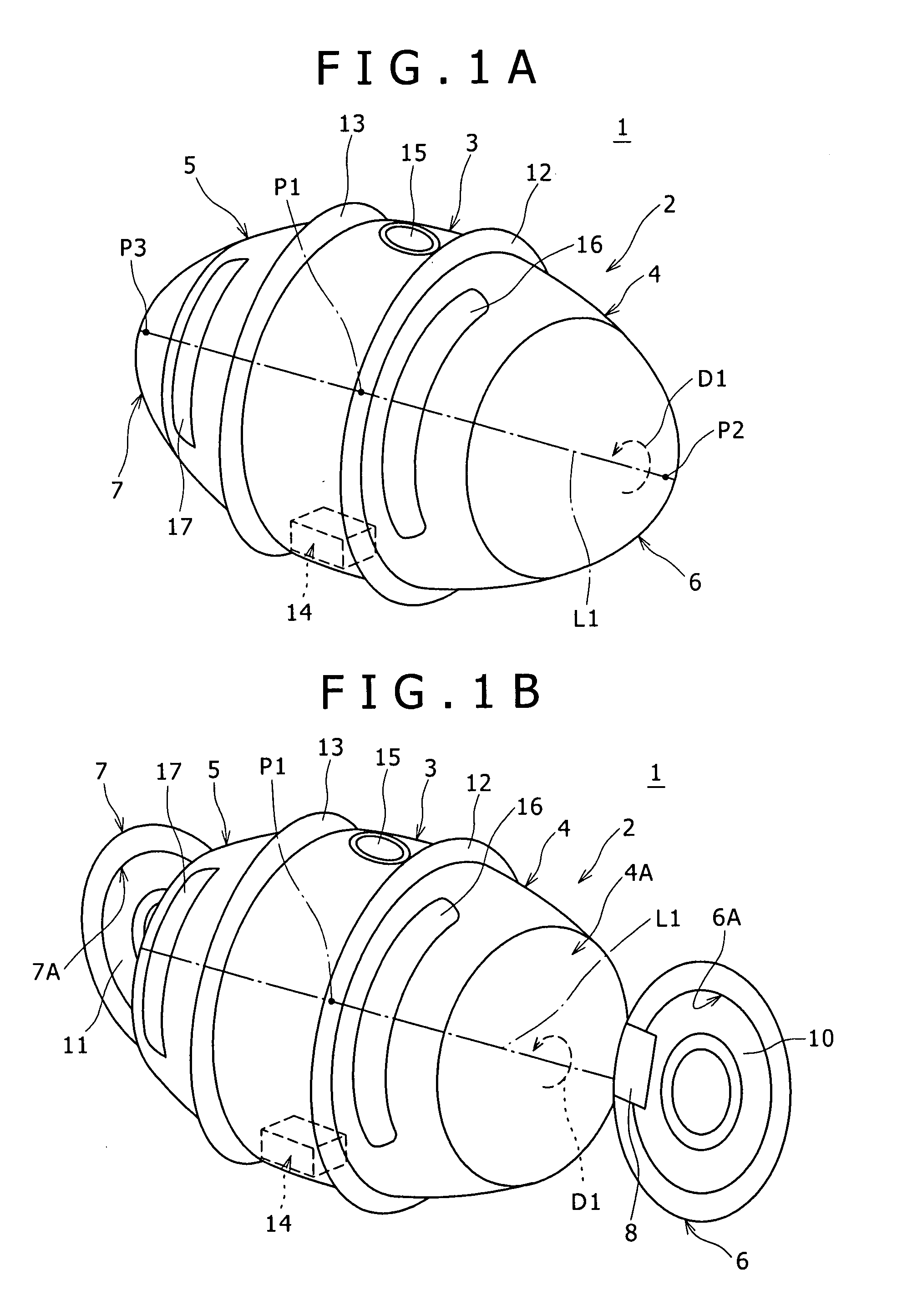
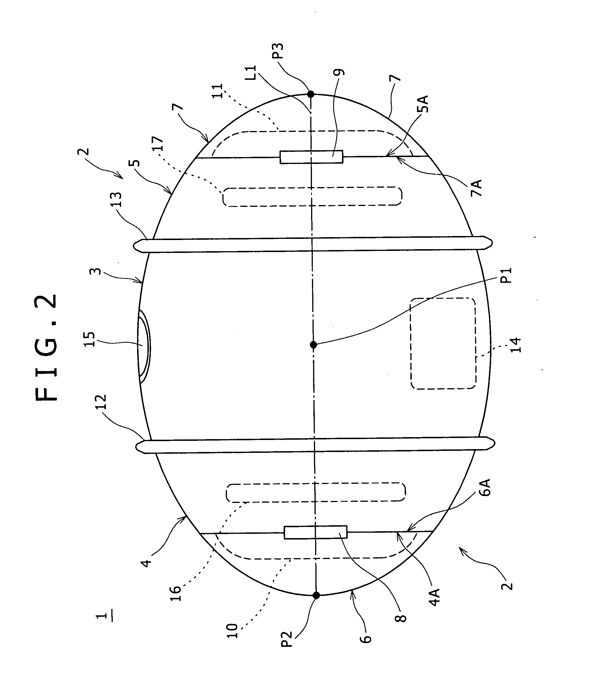
[0028] Referring first to FIGS. 1A and 1B, there is shown a music reproduction robot apparatus to which the present invention is applied. The music reproduction robot apparatus is generally denoted by 1 and includes an apparatus housing 2 of a substantially ellipsoidal shape. The apparatus housing 2 is hereinafter referred to as an ellipsoidal housing member 2. The ellipsoidal housing member 2 includes a housing central member 3 provided at a central portion thereof and having a substantially barrel shape. The ellipsoidal housing member 2 further includes a first housing rotatable member (hereinafter referred to as housing right side rotatable member) 4 having a substantially circular truncated conical shape and positioned at one of a pair of mutually opposing end portions of the housing central member 3 (the one end portion is hereinafter referred to as right side end portio...


PUM


Abstract

A traveling apparatus, including a housing, first and second wheels, a wheel driving section, and a control section. The first and second wheels are supported for individual rotation in one and the other direction around a common axis on the housing. The wheel driving section is configured to drive the first and second wheels to rotate individually. The control section is configured to control the wheel driving section and is operable to control, when traveling of the housing which is traveling is to be stopped, the wheel driving section to drive the first and second wheels to rotate in different conditions from each other so that the housing is revolved toward a first one of the leftward and rightward directions with respect to a traveling direction of the housing once and then revolved toward a second one of the leftward and rightward directions to stop the housing.

Description

CROSS REFERENCES TO RELATED APPLICATIONS [0001] The present invention contains subject matter related to Japanese Patent Application JP 2005-236027 filed with the Japanese Patent Office on Aug. 16, 2005, the entire contents of which being incorporated herein by reference. BACKGROUND OF THE INVENTION [0002] 1. Field of the Invention [0003] This invention relates to a traveling apparatus and a traveling stopping method, and more particularly to a two-wheel traveling apparatus and a traveling stopping method suitably applicable to a music reproduction robot apparatus which includes first and second wheels supported for rotation in the opposite directions around the same axis of rotation and can travel with the first and second wheels driven to rotate. [0004] 2. Description of the Related Art [0005] A coaxial two-wheeled vehicle in the past is configured such that a base is supported for tilting motion on a wheel shaft extending between a pair of wheels. Further, if the load to the base...

Claims


Application Information

Patent Timeline
Patent Type & Authority Applications(United States)
IPC IPC(8): A63H17/34B62D11/02B62D61/06
CPCA63H11/00A63H17/262B62D61/04
Inventor ISHIHARA, ATSUSHIKOKUBO, WATARU
Owner SONY CORP
Why Eureka
Try Eureka