Spinal Fusion Cage, Method of Design, and Method of Use

a fusion cage and spine technology, applied in the field of expandable fusion cages, can solve the problems of insufficient stability of the anterior approach to the spinal fusion, blood vessels, and disadvantages of the procedure, and achieve the effect of preventing backward motion

Inactive Publication Date: 2007-02-22
ABERNATHIE DENNIS LEE +1
View PDF6 Cites 256 Cited by
  • Summary
  • Abstract
  • Description
  • Claims
  • Application Information

AI Technical Summary

Benefits of technology

[0015] In another aspect of the present invention, the housing portions of the fusion cage include at least one ridge extending across at le...

Problems solved by technology

Although ALIF is common, the procedure suffers from disadvantages.
In cases where patients have a “tall” disc, or where there is instability (such as with isthmic spondylolistheses), an anterior approach to the spinal fusion may not provide adequate stability.
Further, the procedure is performed in close proximity to the large blood vessels that go to the legs, thereby risking damage to these blood vessels, which can result in excessive blood loss.
In dealing with male patients, another unique risk arises.
A problem common to many fusion cages, regardless of method of insertion, concerns maintaining or restoring the normal anatomy of the fused spinal segment.
Such cages may l...

Method used


Image

  • Spinal Fusion Cage, Method of Design, and Method of Use
  • Spinal Fusion Cage, Method of Design, and Method of Use
  • Spinal Fusion Cage, Method of Design, and Method of Use

Examples


Embodiment Construction

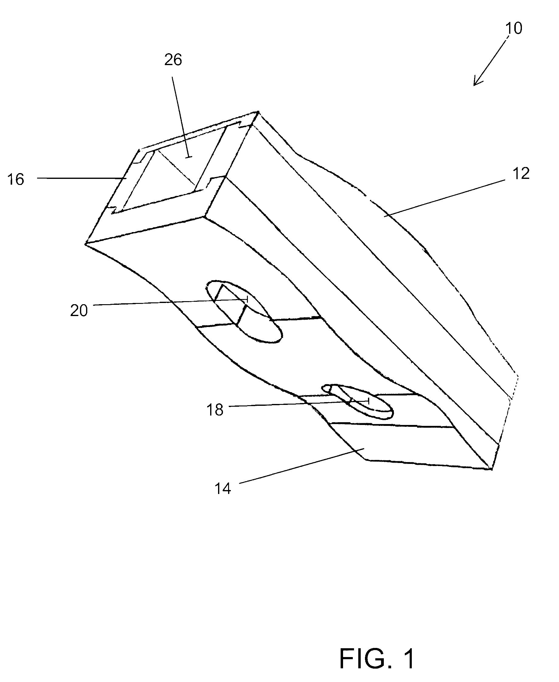
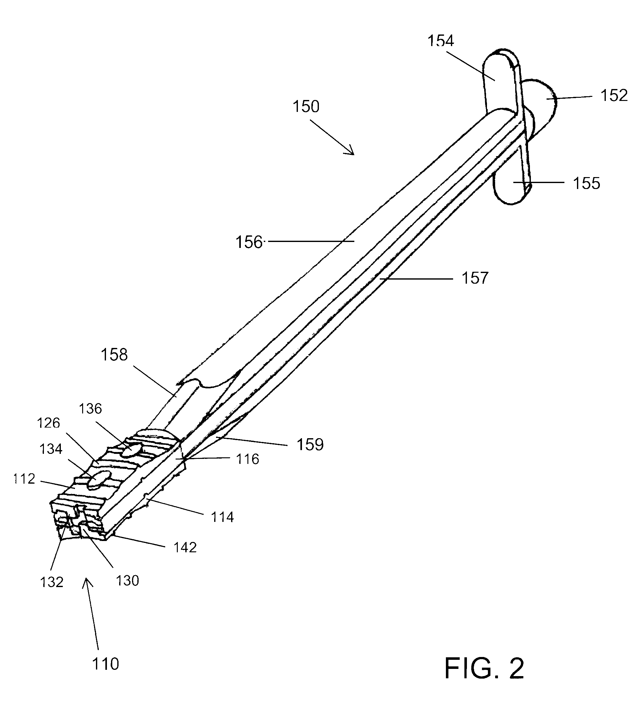
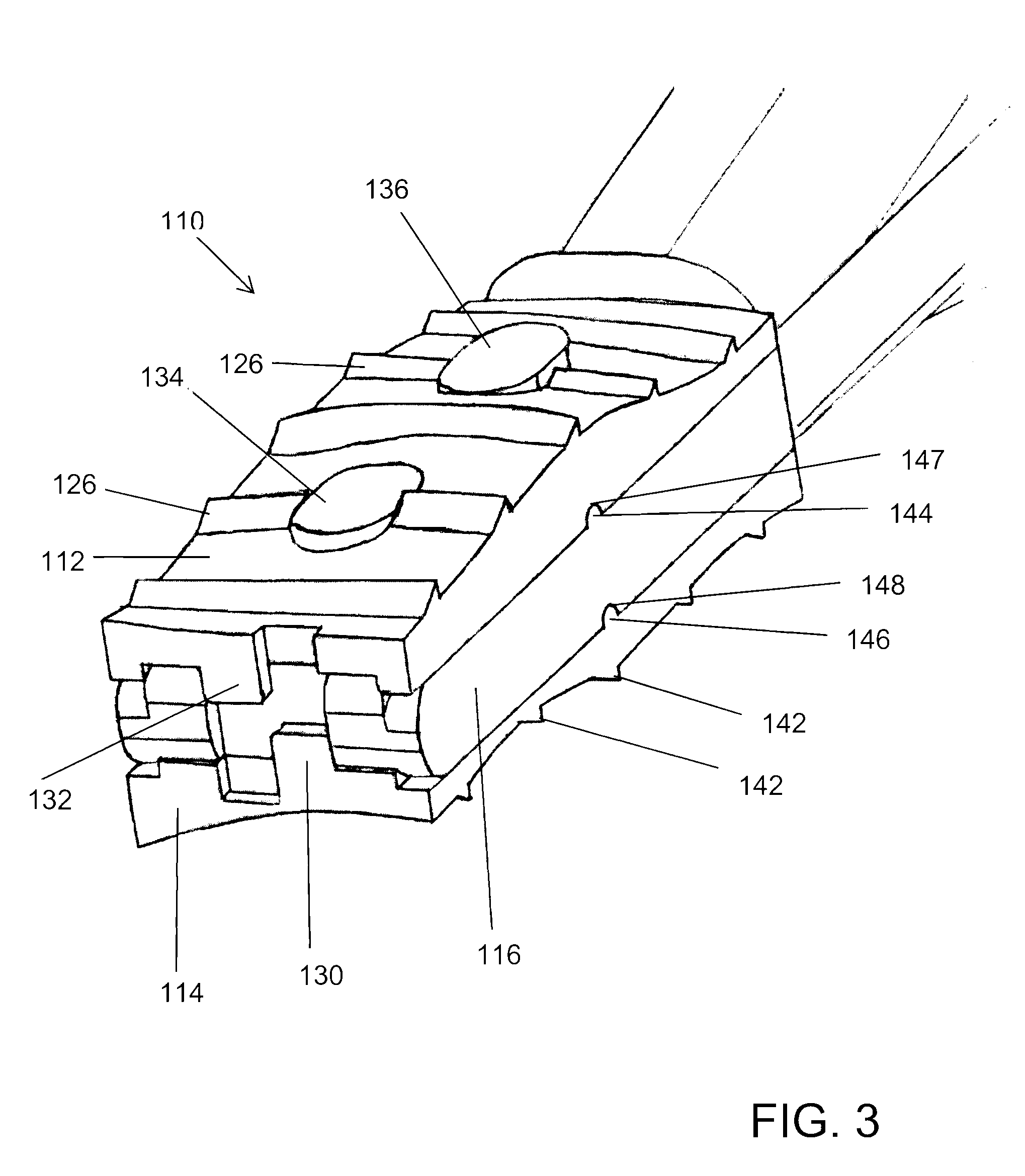
[0030] Before turning to a detailed description of the present invention, it should be noted that the terms “upper” and “lower” are used herein to distinguish various features or parts of the present invention. As these words are used herein, they refer to the relative position of the described part when implanted into a human body, and when that human body is erect. The terms are used for clarity of understanding only, and are not intended to place any specific limitations on the invention described herein. The same holds true for other variations on the words “upper,”“lower,”“upward,”“downward,” and the like.

[0031] The phrase “interior surface” or some variant thereof is also used herein, and refers generally to a surface of a device that disposed toward an interior of the device when the device is assembled.

[0032] The phrase “fixedly attached” is used herein to indicate a fixed attachment of any sort (i.e. one that is not readily releasable with damaging the device). It is cont...


PUM


Abstract

A fusion cage of the present invention includes a first housing portion, a second housing portion, and an insert portion adapted to be received therebetween, wherein the geometry of the fusion cage corresponds substantially to the geometry of a void into which the fusion cage is to be inserted. Also described is a novel tool for insertion of a fusion cage and a novel method for designing a fusion cage or other surgical implant for filling a void identified within a patient.

Description

CROSS-REFERENCE TO RELATED APPLICATIONS [0001] This application is a continuation-in-part of U.S. patent application Ser. No. 11 / 081,162, filed on Mar. 16, 2005. U.S. patent application Ser. No. 11 / 081,162 is hereby incorporated herein by reference in its entirety.STATEMENT REGARDING FEDERALLY SPONSORED RESEARCH OR DEVELOPMENT [0002] Not Applicable. INCORPORATION BY REFERENCE OF MATERIAL SUBMITTED ON A COMPACT DISC [0003] Not Applicable. BACKGROUND OF THE INVENTION [0004] The present invention relates generally to an implantable device for promoting the fusion of adjacent bony structures, and a method of using the same. More specifically, the present invention relates to an expandable fusion cage that may be inserted into an intervertebral space, and a method of using the same. [0005] Fusion cages provide a space for inserting a bone graft between adjacent portions of bone. Such cages are often made of titanium and are hollow, threaded, and porous in order to allow a bone graft cont...

Claims


Application Information

Patent Timeline
IPC IPC(8): A61F2/44
CPCA61F2/4455A61F2002/30383A61F2002/30556A61F2002/30604A61F2002/30777A61F2002/30785A61F2002/30331A61F2002/448A61F2220/0025A61F2250/0006A61F2250/0009A61F2/447A61F2/4611A61F2002/4475A61F2002/30593
Inventor ABERNATHIE, DENNIS LEEPFEIFFER, FERRIS MICHAEL
Owner ABERNATHIE DENNIS LEE
Why Eureka
Try Eureka