Deployable triangular truss beam with orthogonally-hinged folding diagonals

a triangular truss and orthogonal bending technology, applied in the direction of girders, joists, cranes, etc., can solve the problems of unsatisfactory combination of features of the truss system disclosed in the prior art, undue complexity, and undesirable characteristics of the art truss

Inactive Publication Date: 2007-03-01
CPI TECH
View PDF20 Cites 57 Cited by
  • Summary
  • Abstract
  • Description
  • Claims
  • Application Information

AI Technical Summary

Benefits of technology

[0007] Accordingly, the present invention is directed to deployable triangular truss beam systems with orthogonally-hin...

Problems solved by technology

Typically, truss systems disclosed in the prior art lack an optimal combination of features.
Further, some prior art trusses have undesirable characteristics including undue complexity; inability to move in a coordinated and synchronous manner; requirements for a dedicated deployer; lack of compactability, reconfigurability, and multi-functional uses; and high costs.
Fewer still are cap...

Method used


Image

  • Deployable triangular truss beam with orthogonally-hinged folding diagonals
  • Deployable triangular truss beam with orthogonally-hinged folding diagonals
  • Deployable triangular truss beam with orthogonally-hinged folding diagonals

Examples


Embodiment Construction

[0039] Reference will now be made in detail to embodiments of the present invention, examples of which are illustrated in the accompanying drawings.

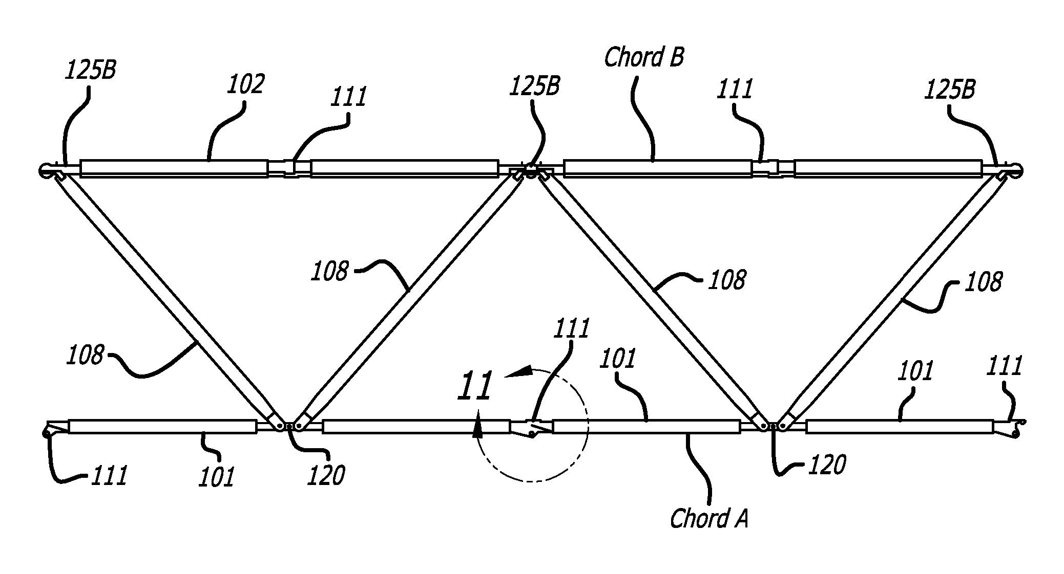
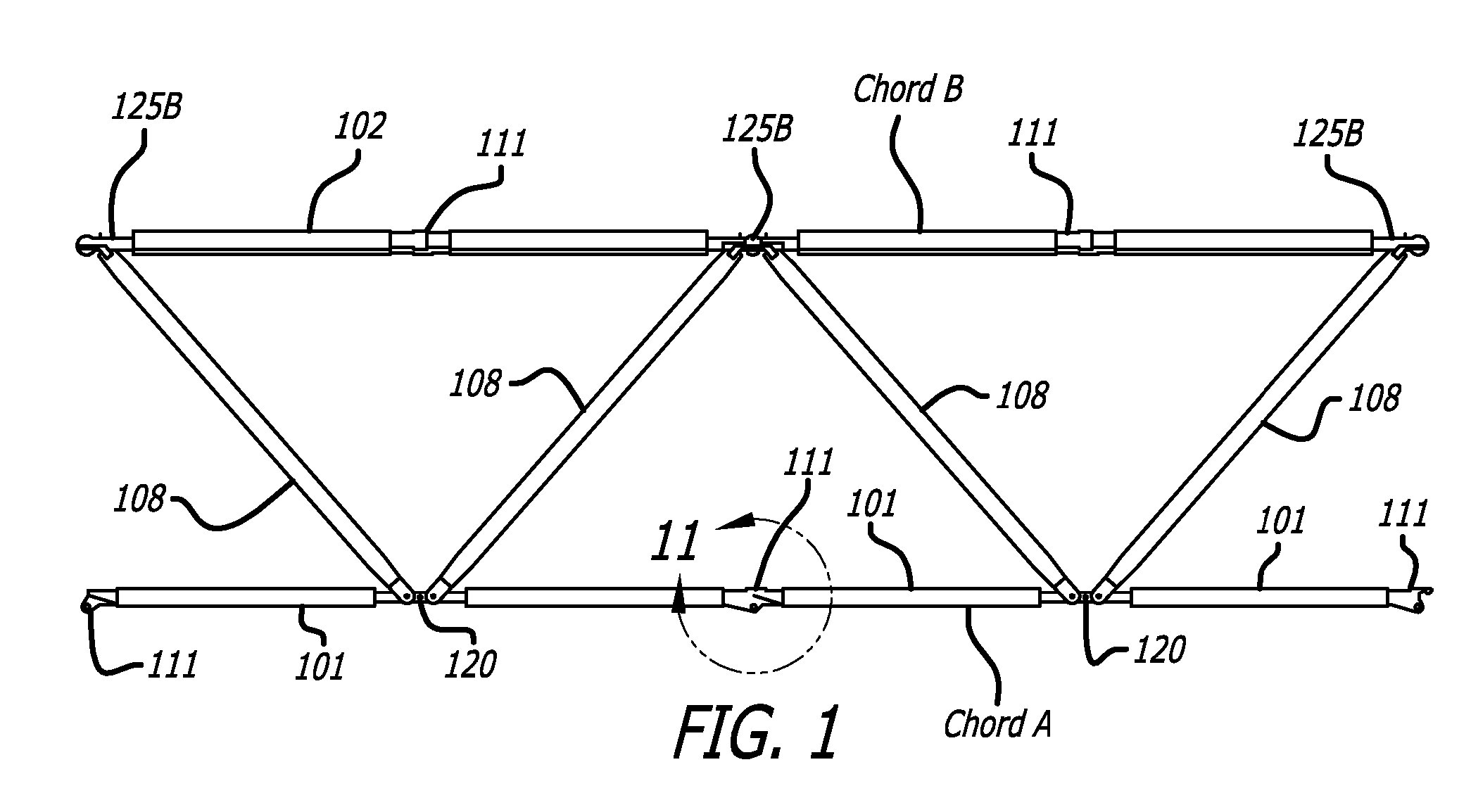
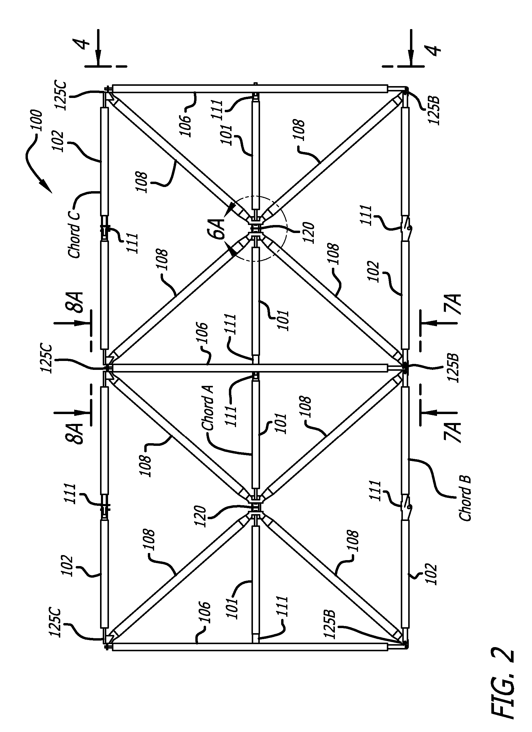
[0040]FIGS. 1-4 disclose the general configuration of an embodiment of a two-bay portion of a basic single triangular deployable truss beam in an extended or deployed state. In the embodiment illustrated in FIGS. 1 to 4, the deployed portion of truss beam 100 is comprised of a series of planar trusses in a Warren pattern. The illustrated embodiment provides a triangle-shaped truss wherein three truss chords, Chord A, Chord B, and Chord C (see FIG. 2), form longitudinal chords. Chord A is a chord that connects base joints 120 of individual truss segments as illustrated in FIGS. 1-4. Chord A, also referred to herein as the “Apex chord”, can also connect to an end mount frame (not shown) as discussed in U.S. Pat. No. 7,028,442. The two other longitudinal chords, Chords B and C, are also oriented substantially along the truss beam's longitu...


PUM


Abstract

A synchronously deployable tetrahedral truss beam with orthogonally-hinged diagonals, having uniquely-connected transverse members and folding chordal members, where a plurality of bays can extend and retract in a coordinated manner without need for a deployment canister mechanism or other assembling means. The triangular cross-section truss can be adapted to deploy pre-attached panels or nodally-attached payload components. These triangular beams can be mounted side-by-side with a common chord to create a synchronously deployable trapezoidal cross-section beam or space-frame. Both the triangular and trapezoidal configurations can be adapted to deploy with a prescribed curvature of the longitudinal axis, and form perimeter trusses which can be post-tensioned for maximum structural performance.

Description

RELATED APPLICATION [0001] This application claims the benefit of and priority to U.S. Provisional Application Ser. No. 60 / 711,670, filed Aug. 29, 2005, the contents of which are incorporated by reference herein in its entirety.FIELD OF THE INVENTION [0002] The present invention generally relates to deployable triangularly-shaped truss systems, and more particularly discloses triangular truss systems having joints that allow for uniform and synchronous retraction and extension of triangularly shaped truss beams. BACKGROUND OF THE INVENTION [0003] There have been many attempts to design a practical, compact, folding or flexible truss system which can transition easily between retracted and extended states when the truss system is situated in varying operating environments. Prior art truss systems were designed to exhibit specific characteristics including low size / volume ratio; high kinematic stability; simplicity and reliability; high compactability; or high structural efficiency in...

Claims


Application Information

Patent Timeline
IPC IPC(8): E04B1/18
CPCE04B1/3441E04B2001/1927E04B2001/1984E04C3/005E04C2003/0495
Inventor MERRIFIELD, DONALDFLETCHER, JAMES W.
Owner CPI TECH
Why Eureka
Try Eureka