Nutplate bond strength tester unit

a technology of bond strength and tester, which is applied in the direction of mechanical means, instruments, manufacturing tools, etc., can solve the problems of time-consuming and labor-intensive substrate disassembly from adjoining structures, and achieve the effects of sufficient bond strength, quick and easy nutplate replacement, and no risk of subsequent post-assembly nutplate separation

Active Publication Date: 2007-03-01
PHYSICAL SYST
View PDF1 Cites 6 Cited by
  • Summary
  • Abstract
  • Description
  • Claims
  • Application Information

AI Technical Summary

Benefits of technology

[0009] In the event of inadequate bond strength attachment of the nutplate to the substrate, the tester unit will forcibly separate the nutplate from the substrate. Such nutplate separation thus provides a clear indication of insufficient bond strength attachment, and the separated nutplate can be replaced. Conveniently, the tester unit is employed at a early manufacturing phase wherein the substrate blind side is still accessible for quick and easy nutplate replacement. Thereafter, a substrate carrying one or more nutplates which are adhesively bonded thereto each with sufficient bond strength may be assembled with adjoining structural components to render the substrate blind side inaccessible, with little or no risk of subsequent post-assembly nutplate separation from the substrate.

Problems solved by technology

While such adhesive mounted nutplates of the above-described type, installed at the blind side of a substrate, accommodate quick and easy subsequent assembly with a mating fastener element, problems can arise when the bond strength is inadequate to support a subsequent load during normal use.
When this failure mode occurs following normal substrate installation in an arrangement which renders the blind side of the substrate substantially inaccessible, remedial action can require time-consuming and labor-intensive substrate disassembly from adjoining structures, e.g., such as adjacent substrate panels and frame components in an aircraft or the like.

Method used


Image

  • Nutplate bond strength tester unit
  • Nutplate bond strength tester unit
  • Nutplate bond strength tester unit

Examples


Embodiment Construction

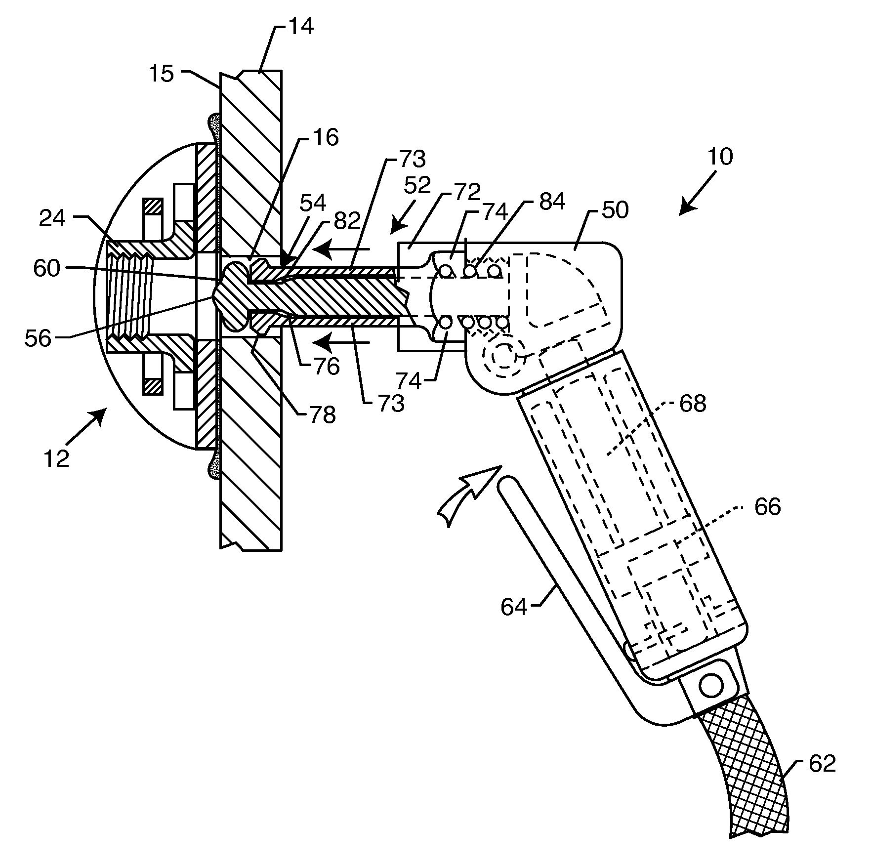
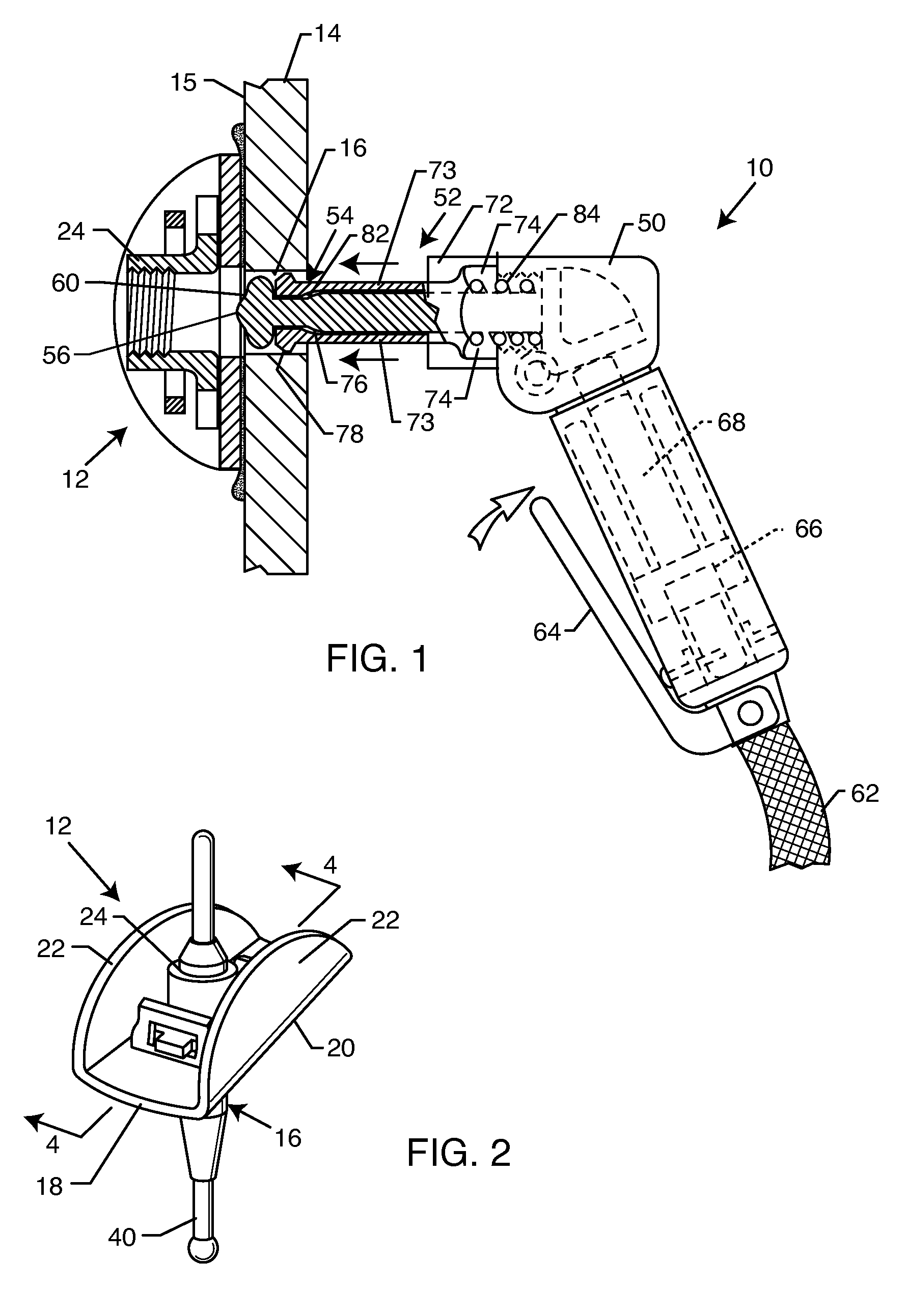
[0029] As shown in the exemplary drawings, a bond strength tester unit referred to generally in FIGS. 1 and 8-10 by the reference numeral 10 is provided for testing and confirming adequate adhesive bond strength attachment of an attachment component such as a nutplate or nutplate assembly 12 onto a substrate 14, such as on a rear or blind side 15 of the substrate 14 in substantial alignment with an access opening 16 formed in the substrate. In the normal event of adequate bond strength attachment to the substrate 14, the nutplate 12 will remain in place in response a test force of selected magnitude applied by the tester unit 10. However, in the case of inadequate bond strength, the nutplate 12 will separate from the substrate 14 and thereby indicate a need for a replacement nutplate affixed with adequate bond strength.

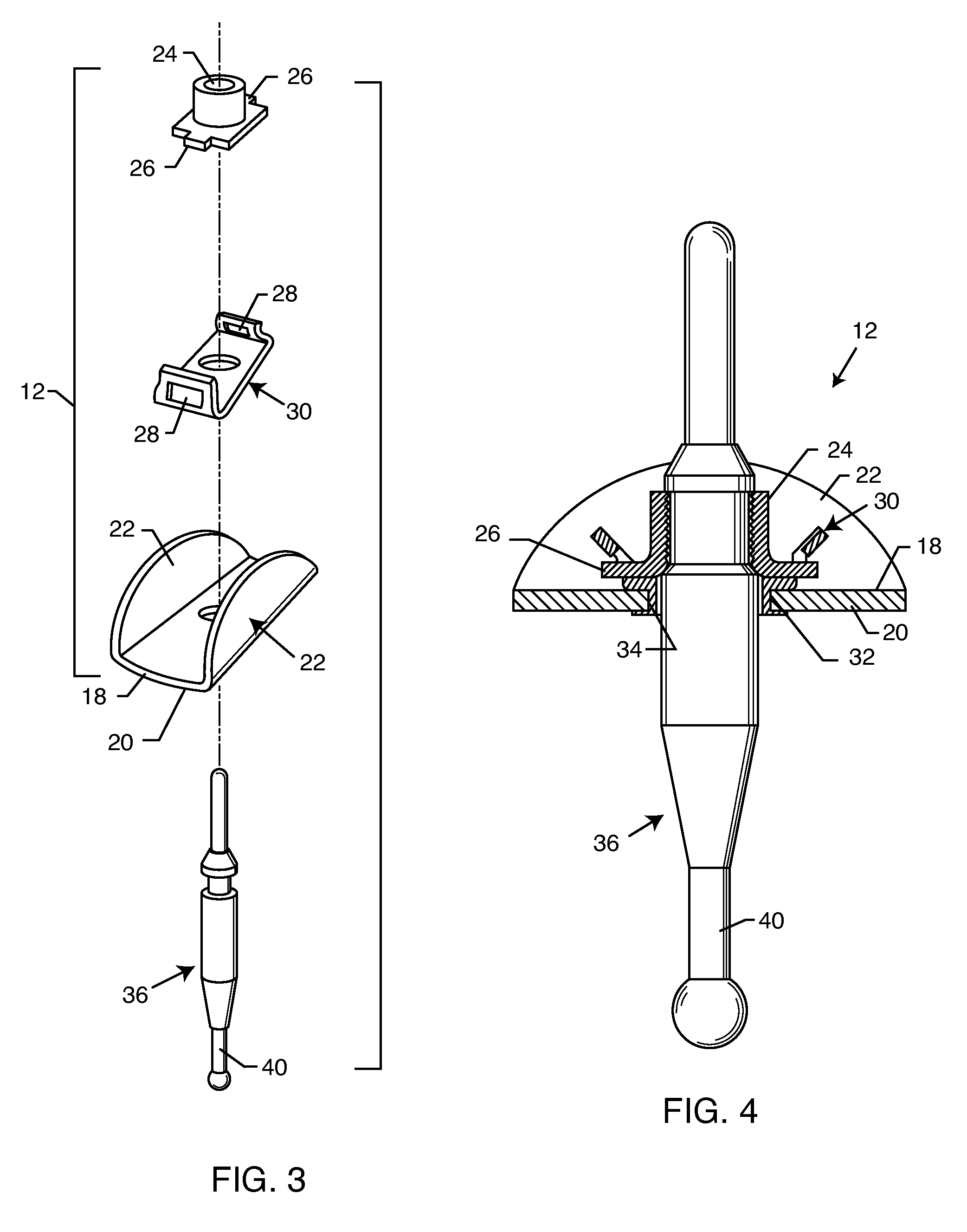
[0030] The bond strength tester unit 10 of the present invention is particularly useful with a nutplate or nutplate assembly 12 of the general type shown and describ...


PUM

PropertyMeasurementUnit
bond strength testeraaaaaaaaaa
bond strengthaaaaaaaaaa
forceaaaaaaaaaa

Abstract

A bond strength tester unit is provided for testing adhesive bond strength of a nutplate or the like attached to a substrate, such as by adhesive bonded attachment to a blind side of the substrate in substantial alignment with a substrate opening. The nutplate may be constructed according to U.S. Pat. No. 5,013,391, and carries a fastener element such as a threaded nut or the like for subsequent connection with a mating fastener element such as a threaded bolt or the like passed through the substrate opening. The tester unit includes a tool tip having a reaction head for engaging the substrate, in combination with an actuator pin for applying a test force of selected magnitude against the adhesively bonded nutplate. In the event of inadequate bond strength, the actuator pin will separate the nutplate from the substrate.

Description

BACKGROUND OF THE INVENTION [0001] This invention relates generally to a system and method for testing and verifying adequate bond strength attachment of an adhesively bonded attachment component such as a nutplate or the like affixed to a selected substrate. More specifically, this invention relates to a bond strength tester unit and method for quickly and easily testing nutplate bond strength attachment, e.g., to a blind side of a substrate. In particular, this invention relates to a bond strength tester unit for use with an adhesive bonded nutplate of the general type disclosed in U.S. Pat. No. 5,013,391. [0002] In many manufacturing environments, it is necessary or desirable to install components onto a blind or reverse side of a supporting substrate. As one common example, nutplates are well known in the automotive and aerospace industries for use in mounting a threaded nut or the like onto the blind side of a supporting substrate, typically in alignment with an access opening ...

Claims


Application Information

Patent Timeline
Patent Type & Authority Applications(United States)
IPC IPC(8): G01N3/08
CPCG01N19/04
Inventor HUTTER, CHARLES
Owner PHYSICAL SYST
Why Eureka
Try Eureka