
Check valve

a check valve and valve body technology, applied in the field of check valves, can solve the problems of unsuitable retrofitting of existing check valves, many existing check valves are simply too long or otherwise too large to fit in the available space,

Inactive Publication Date: 2007-03-01
CAMBRIDGE BRASS
View PDF26 Cites 81 Cited by
  • Summary
  • Abstract
  • Description
  • Claims
  • Application Information

AI Technical Summary

Benefits of technology

[0029] the valve seat has an annular valve seat seal mounted within an annular seal recess on a periphery of the valve seat, said sealing means for preventing flow through the check valve when the poppet is in its first position including a fluid seal created by the valve seat seal between the valve seat and the valve body;

Problems solved by technology

This is because should water flow from the residence to the water main (which can occur when there is a pressure drop in the water main caused by, for example, a broken water main or burst fire hydrant), the municipal water supply can be contaminated.
Many existing check valves however have been found to be unsuitable for use in such retrofits for various reasons.
For example, many existing check valves are simply too long or are otherwise too large to fit in the available space.
Others utilize valve mechanisms which do not allow for sufficient flow rates thereby unacceptably reducing residential water pressure.
Other valves have too many moving parts or parts which can fall out of the valves during handling, resulting in difficulties during installation.
Finally, many check valves are simply not suitable for situations where neither of the connections between which the valve is to be mounted, is rotatable, as may be the case when inserting a check valve between a water meter and a supply line in a retrofitting application.
Despite its advantages, poppet-style valves have only seen limited use in residential water supply retrofit applications.
This is because conventional designs result in valves having limited flow rates, valves which are often too large for retrofitting applications, and valves which are difficult to service in the field.

Method used


Image

  • Check valve
  • Check valve
  • Check valve

Examples


Embodiment Construction

[0046] A preferred embodiment of the check valve of the present invention will now be described in the context of an exemplary application of retrofitting a residential water supply system to inhibit backflow from a residence to a water main.

[0047] In a typical residential water supply system, water from a municipal water main is conveyed to an interior wall of the residence through an underground pipe. A water meter which tracks water use by the residence for billing purposes is mounted to this pipe at the residential end. A supply pipe then conveys the water from the water meter to the various outlets within the residence.

[0048] When retrofitting such a residential water supply system to install a check valve, the valve is normally installed between the water meter and the supply pipe. Most typically, the female threaded connector of the supply pipe is disengaged from the male threaded connector of the water meter, the check valve is placed between the two, and the water meter a...


PUM


Abstract

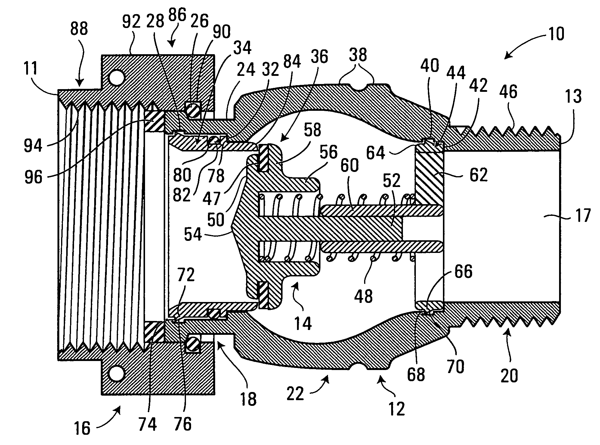
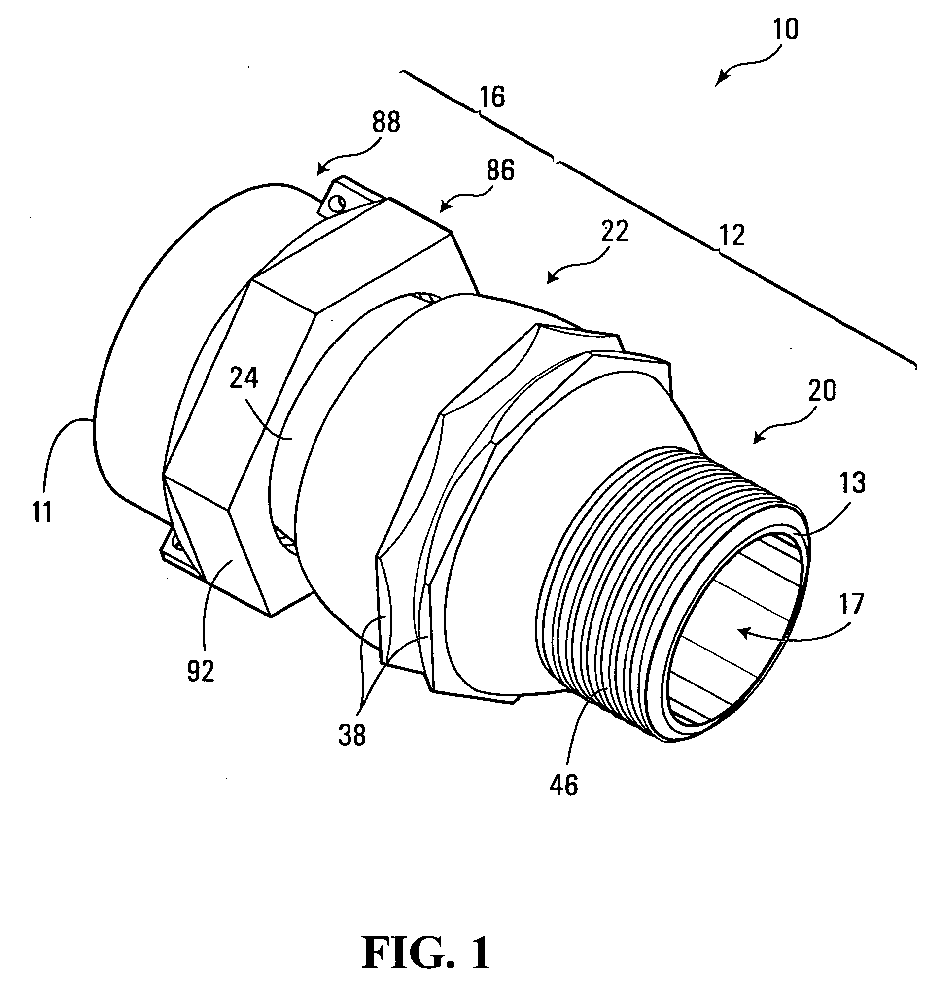
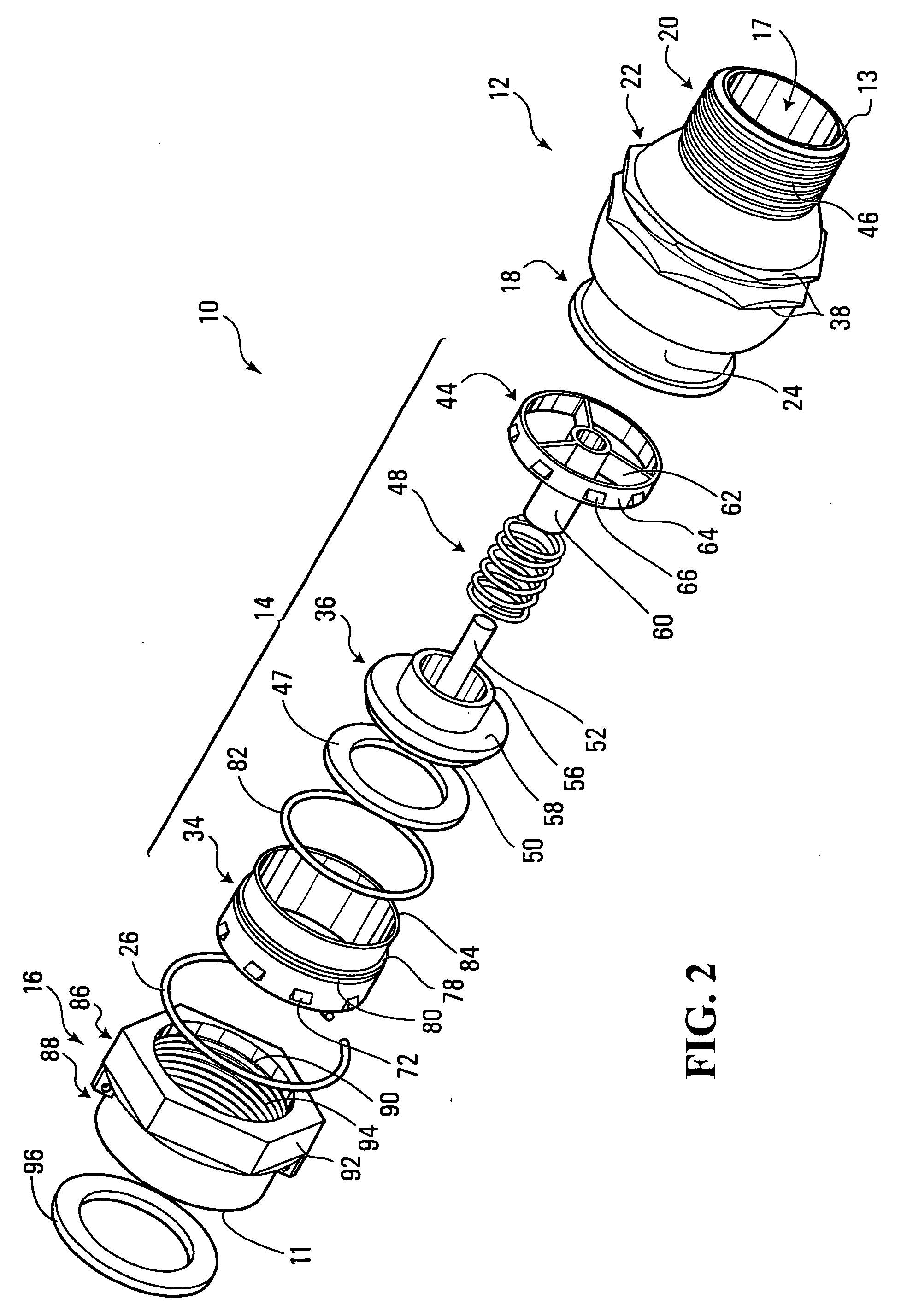
A poppet-style check valve for allowing uni-directional flow in a fluid conducting system. The check valve comprises a valve body, and a poppet mounted therein for reciprocal axial movement between a first position in which the poppet is pressed against a valve seat restricting flow through the check valve, and a second position in which the poppet is spaced from the valve seat permitting flow through the check valve. An inner bore of the valve body is expanded in the area of the poppet to maximize flow through the check valve, and the external dimensions of the check valve are minimized by eliminating a conventional liner between the poppet and the valve body. Additionally, the elements of the valve mechanism are designed such that they lock in place within the valve body during assembly.

Description

FIELD OF THE INVENTION [0001] The invention relates to check valves, and in particular to valves used to prevent backflow through a fluid-conducting passage. BACKGROUND OF THE INVENTION [0002] Particularly in the plumbing and waterworks industries, situations frequently arise where it is important to ensure that a fluid flows through a conduit in only one direction. Such a result is often achieved by introducing a check valve into the conduit. Check valves utilize any of a variety of valve mechanisms, including balls, flaps, swing doors, and poppets to allow fluids to flow in one direction, but not the other. [0003] One exemplary situation in which uni-directional flow is desirable is in residential water supply applications. In such applications, it is preferable to allow water to flow only from the water main into the residence, and not vice versa. This is because should water flow from the residence to the water main (which can occur when there is a pressure drop in the water mai...

Claims


Application Information

Patent Timeline
IPC IPC(8): F16K15/06
CPCF16K15/063F16K27/0209Y10T137/7838Y10T137/7932Y10T137/6086
Inventor NORMAN, JAMIE
Owner CAMBRIDGE BRASS
Learn More