Handgrip powered pressurized air sprayer

Inactive Publication Date: 2007-03-01
WIPPER DANIEL J
View PDF24 Cites 12 Cited by
  • Summary
  • Abstract
  • Description
  • Claims
  • Application Information

AI Technical Summary

Problems solved by technology

The products dispensed can be, more chemically

Method used


Image

  • Handgrip powered pressurized air sprayer
  • Handgrip powered pressurized air sprayer
  • Handgrip powered pressurized air sprayer

Examples


Embodiment Construction

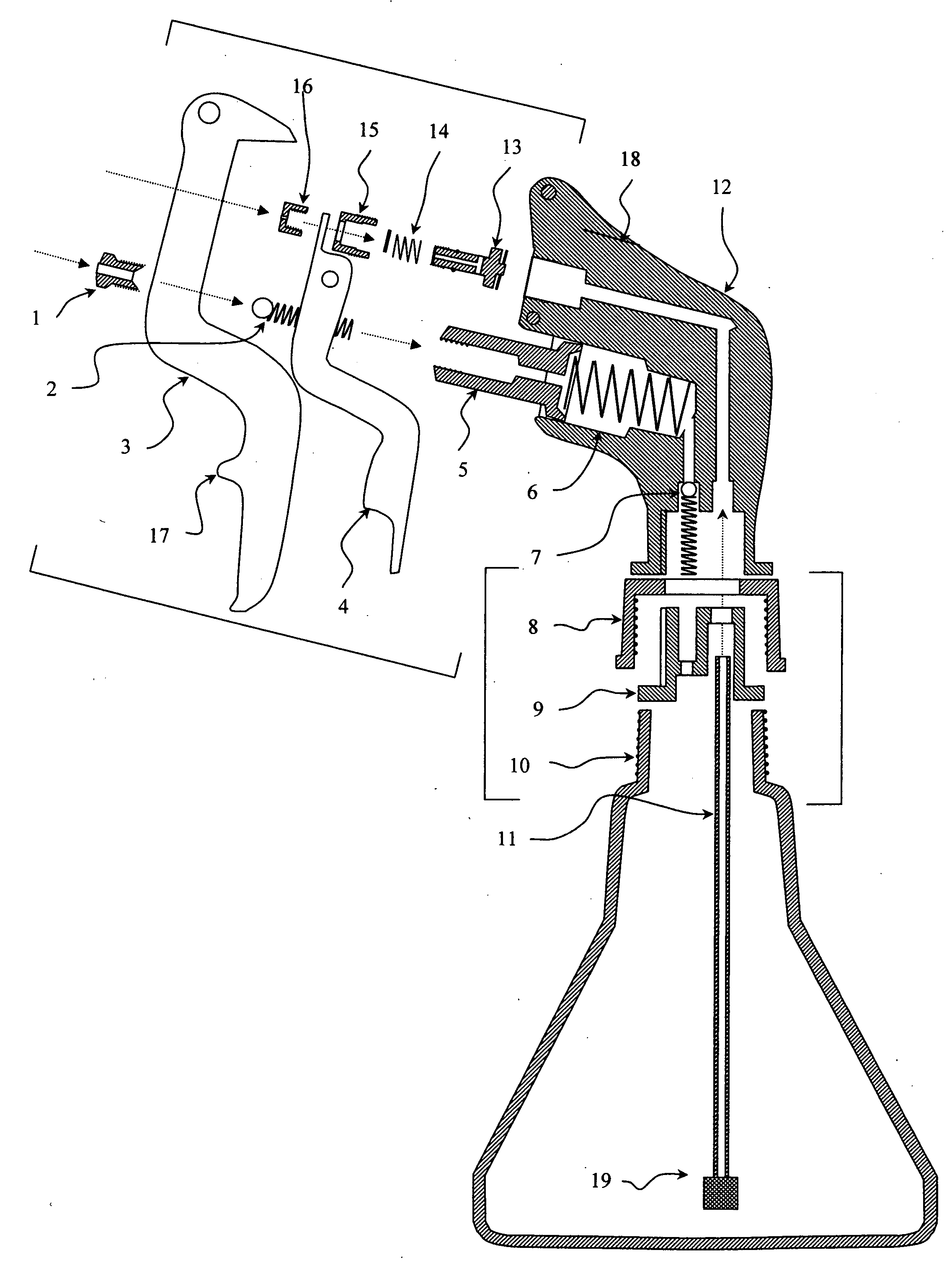
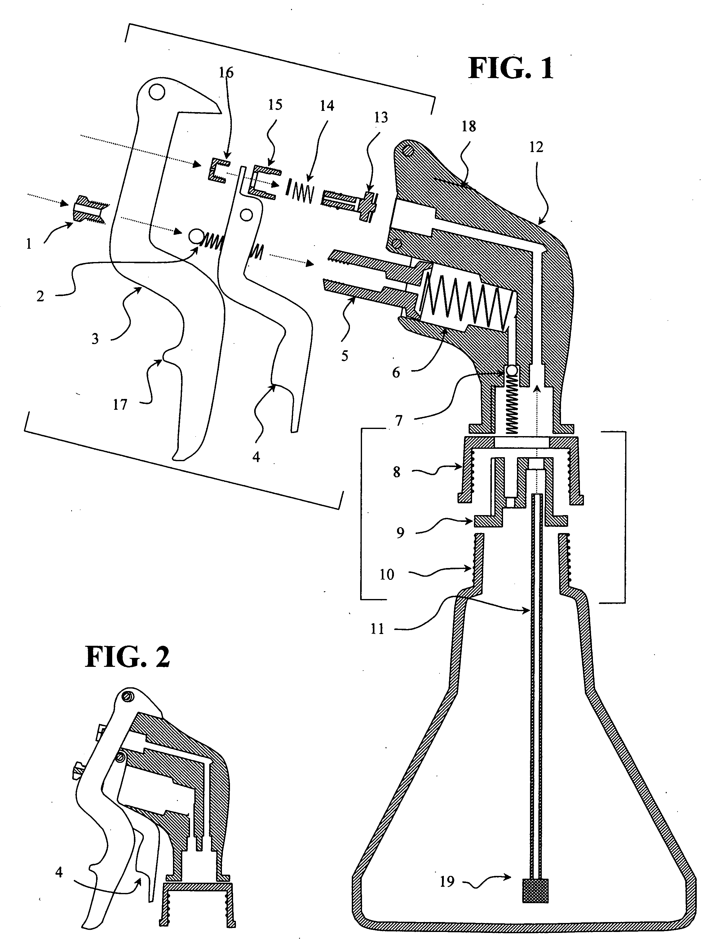
[0016] It is the main objective of this invention to create a pressurized air sprayer where the means for compression is provided in a finger or handgrip squeeze motion.

[0017] One sprayer style of this invention would be to reverse the flow of a common bottle-top trigger sprayer. This is done in a way that the sprayer retains its familiar shapes we are accustomed to. This is an important feature for consumer acceptance. Instead of pumping out fluid, the pump now ingests air, compressing it into the reservoir bottle. The stored air pressure is utilized to dispense product within the reservoir through a conduit that is supplied with a valve and a means for its operation.

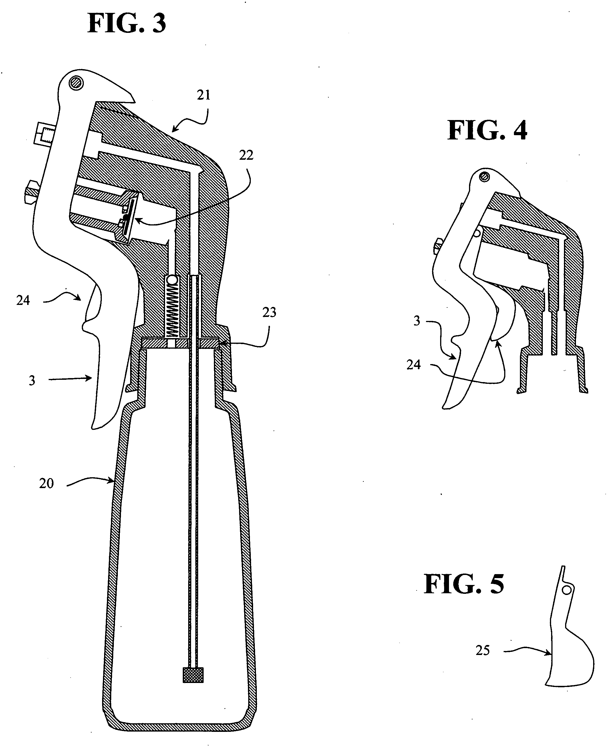
[0018] It is further an objective to produce a one-hand operable, finger or handgrip powered, pressurized-air sprayer. The position of the pumping mechanism could vary and be linked to, or directly attached to the sprayer's pump. Or a traditional pressurized sprayer that is provided a finger or handgrip surface, whic...


PUM


Abstract

The sprayer of this invention is a crossbreed that combines the benefits of a pressurized air sprayer with the convenience a common bottle-top trigger sprayer. However, activating the trigger now has a reverse action causing the related pump to ingest air and the pump's traditional flow direction is now reversed. Air is passed into a reinforced reservoir bottle, near the top, similar to a pressurized air sprayer. Multiple hand-trigger-pulls are used to pre-pressurize air into the reservoir's chamber. A second conduit starting within and near the bottom of the reservoir utilizes air pressure to transfer product within the reservoir to a dispensing-valve. A means is provided to operate the dispensing-valve, which is able to dispense product continuously in-between compression strokes.

Description

FIELD OF THE INVENTION [0001] The present invention relates in a method for combining and improving two existing types of common day sprayers, retaining the most beneficial features of each and creating a hybrid between a bottle-top trigger sprayer and a hand operated, pre-pressurized, air powered sprayer. This new product will fulfill the needs for many applications and create a line of sprayers that are superior to common bottle-top trigger sprayers and more convenient than present day pressurized-air sprayers. More particularly, this invention demonstrates a method of building pressurized-air sprayers that are pre-pressurized utilizing a finger or handgrip squeezing motion. BACKGROUND OF THE INVENTION [0002]U.S. PATENT DOCUMENTS4,196,828 4 / 1980Basil4,235,35311 / 1980Capra4,537,334 8 / 1985Spengler4,872,59510 / 1989Hammett5,183,185 2 / 1993Hutcheson5,522,54706 / 1996Dobbs5,535,95007 / 1996Barriac6,053,37204 / 2000Abedi6,279,784 8 / 2001O'Neill6,527,202 3 / 2003Tseng[0003] U.S. Pat. No. 4,196,828 Ba...

Claims


Application Information

Patent Timeline
IPC IPC(8): A62C11/00B05B9/04
CPCA62C11/00B05B9/0822B05B9/0816
Inventor WIPPER, DANIEL J.
Owner WIPPER DANIEL J
Why Eureka
Try Eureka