Liquid jetting head and method for producing the same

a technology of liquid jetting head and liquid, which is applied in the direction of printing and inking apparatus, etc., can solve the problems of increasing the electric power consumption of the piezoelectric actuator, and achieve the effect of suppressing cross-talk

Active Publication Date: 2007-03-01
BROTHER KOGYO KK
View PDF8 Cites 25 Cited by
  • Summary
  • Abstract
  • Description
  • Claims
  • Application Information

AI Technical Summary

Benefits of technology

[0008] However, when stiffness is high in the piezoelectric actuator at areas thereof overlapping with the pressure chambers, (particularly areas each of which overlaps with a central portion of one of the pressure chambers, and each of which no individual electrode is formed), a driving signal of an electric potential higher than an electric potential of the individual electrode is consequently applied so as to apply a predetermined pressure to the ink in the pressure chamber, thereby increasing an electric power consumption of the piezoelectric actuator. Therefor, for the purpose of improving drive efficiency of the piezoelectric actuator, a structure is demanded which is capable of increasing an amount of deformation of the piezoelectric actuator without increasing the drive voltage. Moreover, it is desirable that the structure is applicable not only to a piezoelectric actuator having multilayered piezoelectric layers but also to a single-layered piezoelectric actuator.
[0009] Therefore, an object of the present invention is to provide a liquid jetting head with excellent drive efficiency of a piezoelectric actuator, and a method of producing the liquid jetting head.

Problems solved by technology

However, when stiffness is high in the piezoelectric actuator at areas thereof overlapping with the pressure chambers, (particularly areas each of which overlaps with a central portion of one of the pressure chambers, and each of which no individual electrode is formed), a driving signal of an electric potential higher than an electric potential of the individual electrode is consequently applied so as to apply a predetermined pressure to the ink in the pressure chamber, thereby increasing an electric power consumption of the piezoelectric actuator.

Method used


Image

  • Liquid jetting head and method for producing the same
  • Liquid jetting head and method for producing the same
  • Liquid jetting head and method for producing the same

Examples


first embodiment

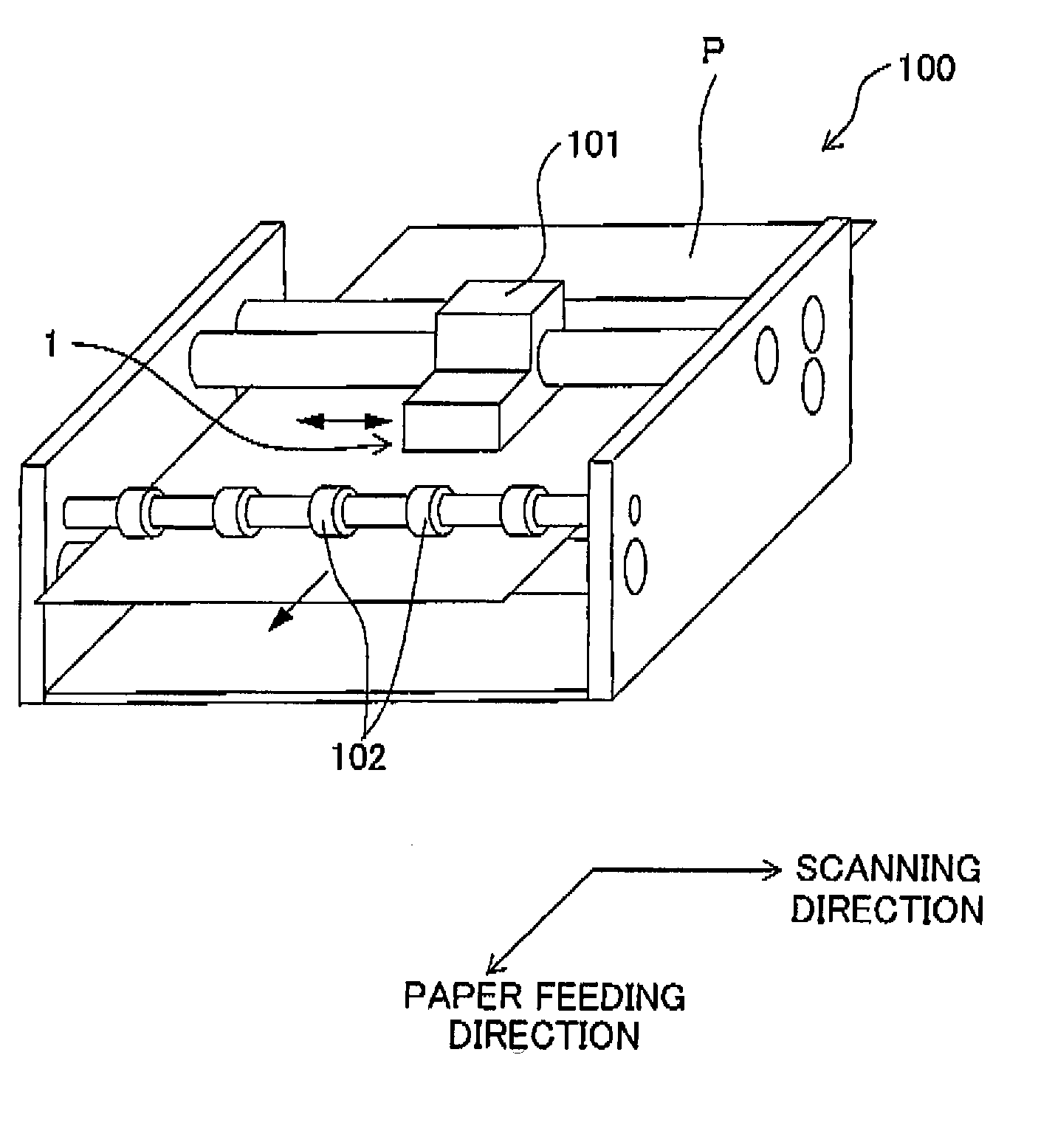
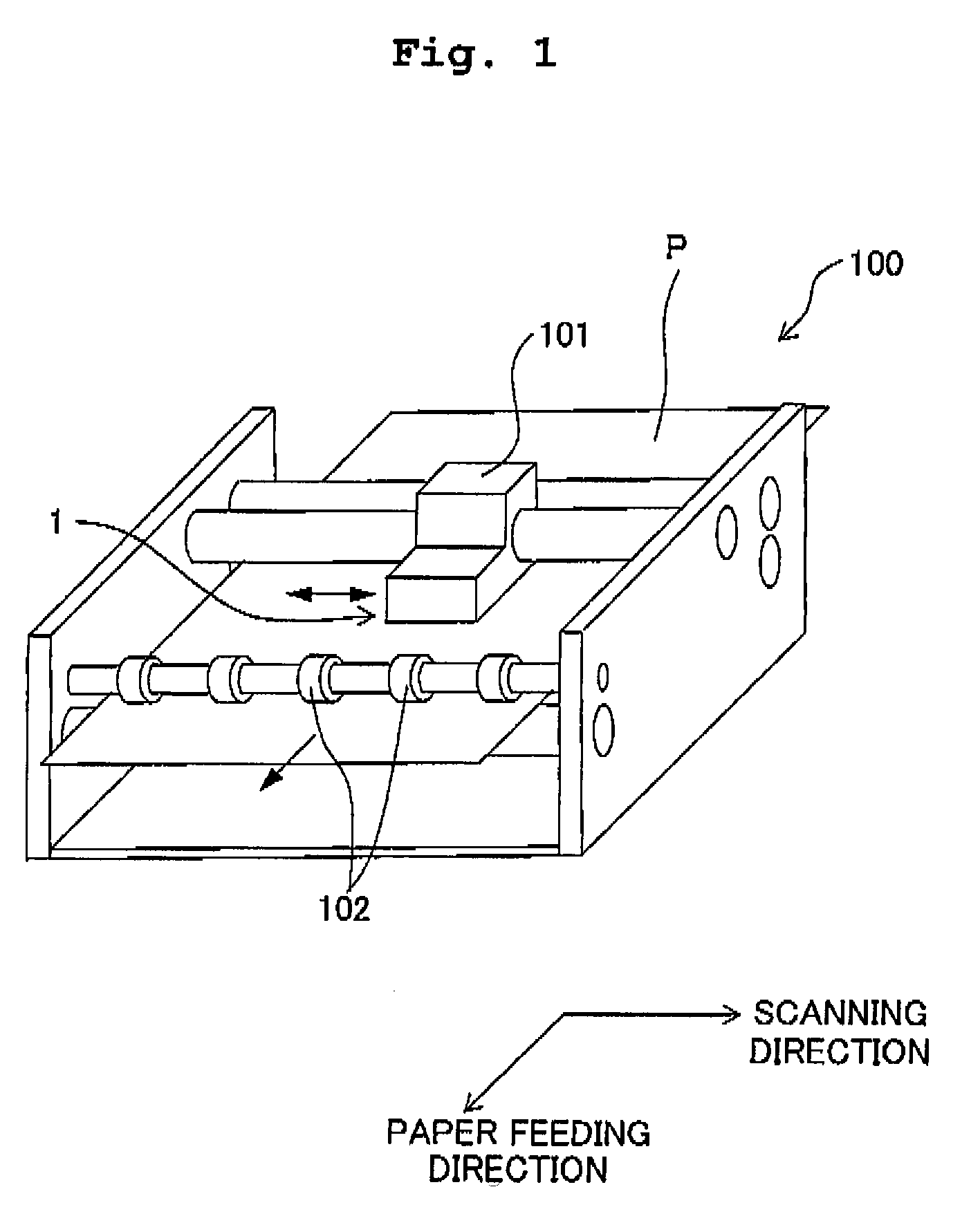
[0067] A first embodiment of the present invention will be described below. The first embodiment is an example in which the present invention is applied to an ink-jet head as a liquid jetting head, which jets an ink onto a recording paper from a nozzle. FIG. 1 is a schematic perspective view of an ink-jet printer in which the ink-jet head according to the first embodiment of the present invention is adopted. As shown in FIG. 1, an ink-jet printer 100 includes a carriage 101 which is movable in a scanning direction (left and right direction in FIG. 1), an ink-jet head 1 of serial type which is provided on the carriage 101 and jets ink onto a recording paper P, and transporting rollers 102 which transport or feed the recording paper P in a paper feeding direction (forward direction in FIG. 1). The ink-jet head 1 moves integrally with the carriage 101 in the scanning direction (left and right direction), and jets ink onto the recording paper P from nozzles 20 (see FIG. 4) which are for...

second embodiment

[0093] Next, an ink-jet head according to a second embodiment of the present invention will be explained referring to FIG. 8. FIG. 8 is a partial cross-sectional view of the ink-jet head. As shown in FIG. 8, an ink-jet head 201 in the second embodiment has a structure substantially similar to the structure of the ink-jet head 1 of the first embodiment, except that the ink-jet head 201 includes a piezoelectric actuator 203 having recesses 239 which formed to be deeper than the recesses 39 in the first embodiment. Therefore, same reference numerals are assigned to parts or components which are similar as those in the first embodiment, and description therefor is omitted.

[0094] The piezoelectric actuator 203 includes a vibration plate 230, a piezoelectric layer 231, an electroconductive layer 235, individual electrodes 232, and dummy electrodes 234, which are substantially similar as those in the first embodiment. Outer grooves 236 and inner grooves 237 (first and second grooves) simi...

first modification

[0102] As shown in FIGS. 12 and 13, a recess 37A may be formed in a piezoelectric actuator 3A at a portion inside of each of the outer grooves 36. The piezoelectric actuator 3A of the first modification has a structure similar to the structure of the piezoelectric actuator 3 in the first embodiment, except that the recess 37A is formed in place of the recess 39 and the inner groove 37. As shown in FIG. 13, a depth of the recess 37A is same as a thickness of the electroconductive layer 35. In other words, there is no electroconductive layer 35 in the piezoelectric actuator 3A at areas thereof in each of which the recess 37A is formed, and the piezoelectric layer 31 is exposed through a lower surface of the recess 37A. In this case, since the recess 37A is not formed in the piezoelectric layer 31, the thickness, of the piezoelectric layer 31, in an area overlapping with the recess 37A is same as a thickness in the area overlapping with the individual electrode 32. Thus, even in a case...


PUM


Abstract

An ink-jet head includes a channel unit in which a plurality of pressure chambers are formed; and a piezoelectric actuator which includes a vibration plate, a piezoelectric layer formed on an upper surface of the vibration plate, and an electroconductive layer formed on an upper surface of the piezoelectric layer. On an upper surface of the piezoelectric actuator, there are formed outer grooves each extended along an area overlapping with the periphery of each of the pressure chambers, and inner grooves each extended along one of the outer grooves at a portion inside of one of the outer grooves. Further, recesses deeper than the thickness of the electroconductive layer is formed in the piezoelectric actuator at portions each located inside of the one of the inner grooves. Accordingly, it is possible to improve a drive efficiency of the piezoelectric actuator.

Description

CROSS-REFERENCE TO RELATED APPLICATION [0001] The present application claims priority from Japanese Patent Application No. 2005-250795, filed on Aug. 31, 2005, the disclosure of which is incorporated herein by reference in its entirety. BACKGROUND OF THE INVENTION [0002] 1. Field of the Invention [0003] The present invention relates to a liquid jetting head which jets or discharges a liquid from a nozzle, and a method of producing the liquid jetting head. [0004] 2. Description of the Related Art [0005] As an ink-jet head which jets an ink onto a recording medium, ink-jet heads having various structures have been proposed or brought into practical use. Among these ink-jet heads, an ink-jet head described in U.S. Pat. No. 6,971,738 includes a channel unit in which a plurality of pressure chambers communicating with nozzles respectively is formed, and a piezoelectric actuator which applies pressure to an ink in the pressure chambers, by changing a volume of the pressure chambers. [0006...

Claims


Application Information

Patent Timeline
Patent Type & Authority Applications(United States)
IPC IPC(8): B41J2/045
CPCB41J2/14233B41J2202/11B41J2002/14491B41J2002/14266
Inventor KATAYAMA, NAOKITAKAHASHI, YOSHIKAZUSUGAHARA, HIROTO
Owner BROTHER KOGYO KK
Why Eureka
Try Eureka