AI technical title is built by Patsnap AI team. It summarizes the technical point description of the patent document.
a diaphragm and optical technology, applied in the field of optical diaphragm and projector, can solve the problems of inability to ensure the silence of the device, the inability of the first light-shielding vanes to cope, etc., and achieve the effects of reducing light quantity, high contrast ratio, and increasing light quantity
Inactive Publication Date: 2007-03-01
SEIKO EPSON CORP
View PDF5 Cites 8 Cited by
Summary
Abstract
Description
Claims
Application Information
AI Technical Summary
This helps you quickly interpret patents by identifying the three key elements:
Problems solved by technology
Method used
Benefits of technology
Benefits of technology
[0014] According to the aspect of the invention, the plurality of light-shielding vanes each include the vane plate and the bearing. The vane plate and the bearing are integrally formed. The thickness of the bearing in the optical axis direction of the light beam is larger than that of the vane plate. The end surfaces in the optical axis direction of the bearing abut on at least one of the base plate and the vane holder. With such arrangement, when the plurality of light-shielding vanes rotate, the plurality of bearings rotate relative to the plurality of the rotary shafts. Herein, the end surfaces of the plurality of bearings abut and slide on at least one of the base plate and the vane holder, while the plurality of vane plates can be prevented from abutting and sliding on the base plate and the vane holder, which allows the plurality of vane plates to be stably rotated along the plane orthogonal to the optical axis of the light beam. In addition, with such arrangement, by attaching the plurality of light-shielding vanes to the base plate and the vane holder via the plurality of rotary shafts in such a manner that adjacent vane plates are spaced apart from each other by a predetermined distance in the optical axis direction of the light beam, the adjacent vane plates can be prevented from abutting and sliding on each other. Accordingly, the plurality of the light-shielding vanes can rotate stably along the plane orthogonal to the optical axis of the light beam.
[0036] The light quantity of the light beam irradiated from the light source device to the optical modulator can be adjusted by the optical diaphragm. Thus, a projection image with high contrast ratio can be realized by controlling the optical diaphragm in accordance with luminance of the image, e.g., by controlling the optical diaphragm to reduce the light quantity for an image that is dark as a whole or to increase the light quantity for an image that is light as a whole.
Problems solved by technology
However, when the light-shielding device disclosed in the Document is installed in a projector and used as an optical diaphragm for adjusting a light quantity of a light beam irradiated by a light source device, the following problem will arise.
However, the first light-shielding vanes are made of a resin material in the light-shielding device disclosed in the Document, so that the first light-shielding vanes cannot cope with such temperature rise caused by the light interception.
However, such arrangement generates a frictional noise due to abutting and sliding of the plurality of light-shielding vanes, thus being unable to ensure silence of the device.
Method used
Image
Click on the blue label to locate the original text in one second.
Reading with bidirectional positioning of images and text.
Examples
first exemplary embodiment
[0047] A first exemplary embodiment of the invention will be described below with reference to the attached drawings.
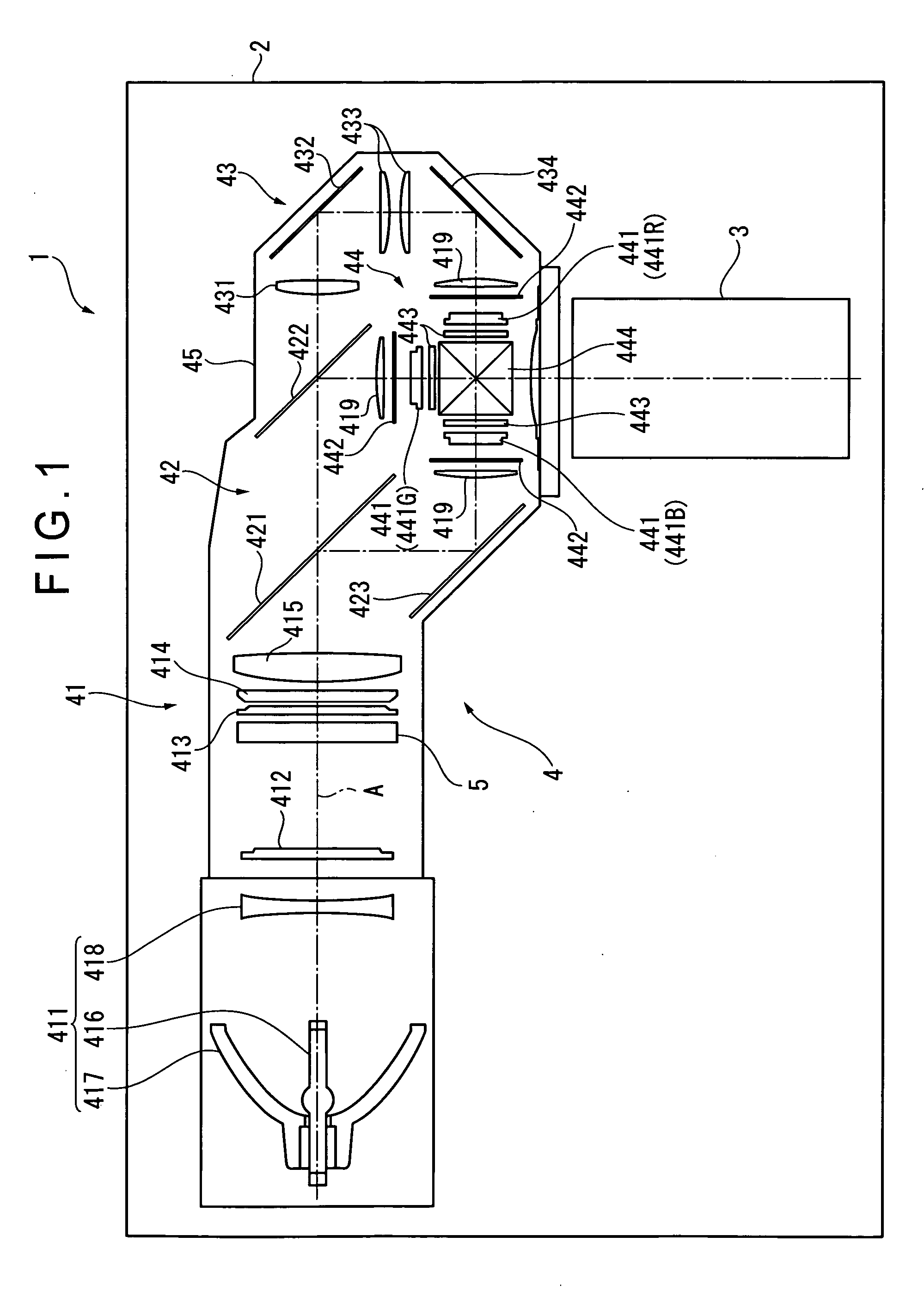
[0049]FIG. 1 is an illustration schematically showing an outline of a projector 1.
[0050] The projector 1 modulates a light beam irradiated from a light source in accordance with image information to form an optical image and projects the formed optical image on a screen (not shown) in an enlarged manner. As shown in FIG. 1, the projector 1 includes an exterior casing 2, a projection lens 3 as a projection optical device, an optical unit 4 and the like.
[0051] Incidentally, although not shown in FIG. 1, a cooling unit including a cooling fan or the like for cooling inside the projector 1, a power source unit for supplying electrical power to each component inside the projector 1, a control board for entirely controlling the projector 1, etc. are arranged in a space not occupied by the projection lens 3 and the optical unit 4 in the ext...
second exemplary embodiment
[0142] Next, a second exemplary embodiment of the invention will be described below with reference to the attached drawings.
[0143] In the description below, the same reference numerals will be attached to the structures and components which are same as the first exemplary embodiment to omit or simplify the detailed description thereof.
[0144]FIG. 5 is an illustration showing a structure of a rotary shaft 63 of the second exemplary embodiment. Note that FIG. 5 shows the rotary shafts 63 disposed in the regions RA, RC out of the regions RA to RD. Here, the rotary shafts 63 disposed in the regions RB, RD are the same as the rotary shafts 63 in the regions RA, RC.
[0145] The second exemplary embodiment is only different from the first exemplary embodiment in the structure of the rotary shaft 53 of the optical diaphragm 5. Other arrangements of the optical diaphragm 5 and the arrangement of the projector 1 are the same as those in the first exemplary embodiment.
[0146] As shown in FIG. ...
PUM
Abstract
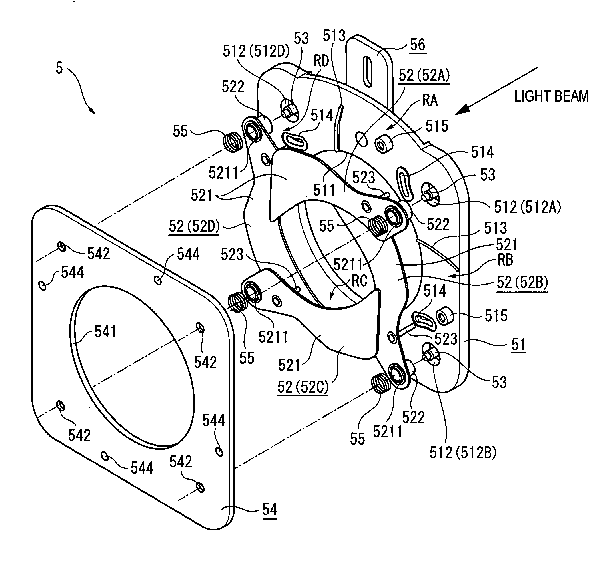
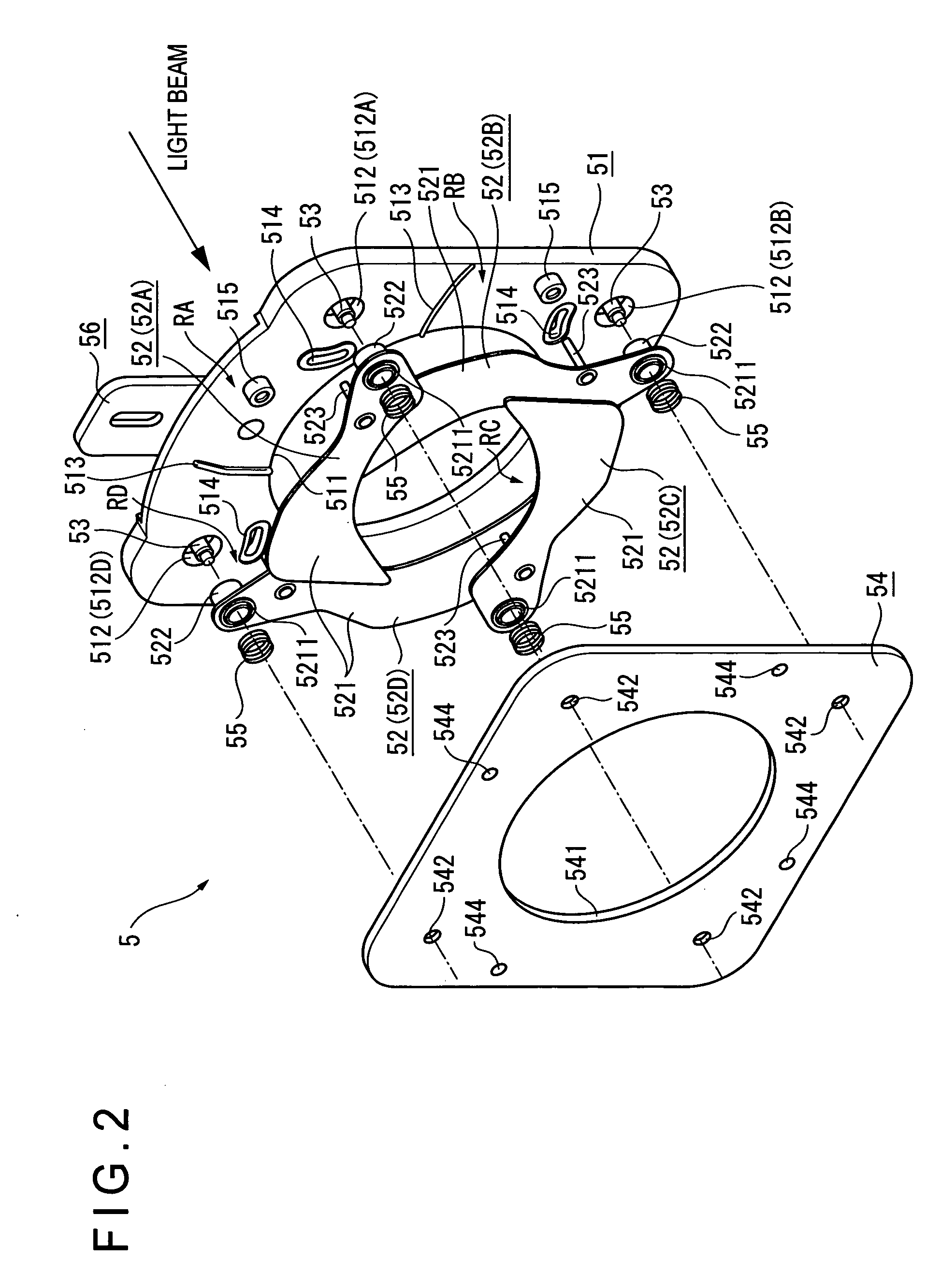
An optical diaphragm for adjusting a light quantity of an incident light beam includes: a base plate extending along a plane orthogonal to an optical axis of the light beam, the base plate having an aperture for transmitting the light beam; a plurality of light-shielding vanes attached to a circumferential portion of the aperture of the base plate in a manner rotatable along the plane orthogonal to the optical axis of the light beam, the light-shielding being rotated to change an aperture area of the aperture for transmitting the light beam to adjust the light quantity of the light beam; a vane holder for pressing the plurality of light-shielding vanes to the base plate in a manner that the light-shielding vanes are rotatable; a plurality of rotary shafts fixed between the base plate and the vane holder, the rotary shafts each rotatably supporting each of the plurality of light-shielding vanes; and a vane-driving mechanism movably attached to the base plate and engaged with the plurality of light-shielding vanes, the vane-driving mechanism moving relative to the base plate to rotate the plurality of light-shielding vanes. The plurality of light-shielding vanes each include a vane plate for intercepting the incident light beam; and a bearing integrally provided to the vane plate, the bearing each allowing each of the rotary shafts to be inserted therein so as to be supported by each of the rotary shafts. The vane plate is perpendicularly attached to the bearing. The plurality of light-shielding vanes move in parallel to each other in an opening and closing direction thereof without crossing with each other.
Description
[0001] The entire disclosure of Japanese Patent Application No. 2005-240899, filed Aug. 23, 2005, is expressly incorporated by reference herein. BACKGROUND [0002] 1. Technical Field [0003] The present invention relates to an optical diaphragm and a projector. [0004] 2. Related Art [0005] There has been employed in a camera a light-shielding device capable of changing an aperture area formed on an optical axis by a plurality of light-shielding vanes that are movable in a plane orthogonal to the optical axis (see, for instance, Document: JP-A-9-189935). [0006] In the light-shielding device disclosed in the Document, the plurality of light-shielding vanes include first vanes that are each made of only a resin material and second vanes that each include at least a portion made of a metal material, the first and second vanes being arranged alternately in an optical axis direction. The second vanes each have a projected portion abutting and sliding on the first vanes or a supporter. With ...
Claims
Application Information
Patent Timeline
Application Date:The date an application was filed.
Publication Date:The date a patent or application was officially published.
First Publication Date:The earliest publication date of a patent with the same application number.
Issue Date:Publication date of the patent grant document.
PCT Entry Date:The Entry date of PCT National Phase.
Estimated Expiry Date:The statutory expiry date of a patent right according to the Patent Law, and it is the longest term of protection that the patent right can achieve without the termination of the patent right due to other reasons(Term extension factor has been taken into account ).
Invalid Date:Actual expiry date is based on effective date or publication date of legal transaction data of invalid patent.
Patent Type & AuthorityApplications(United States)

