Method for inserting a ceramic functional body in a tubular metal housing and a device thus produced

a technology of ceramic functional bodies and tubular metal housings, which is applied in the direction of mechanical equipment, machines/engines, separation processes, etc., can solve the problems of ceramic functional bodies with large diameter tolerances, ceramic functional bodies are rather expensive, and ceramic functional bodies are damaged

Inactive Publication Date: 2007-03-01
HEINRICH GILLET GMBH & CO KG
View PDF7 Cites 0 Cited by
  • Summary
  • Abstract
  • Description
  • Claims
  • Application Information

AI Technical Summary

Benefits of technology

[0009] It is therefore an object of the present invention to provide a method by which an after-the-fact sizing of the housing can be performed without the risk of damage to the ceramic functional body or to the support mat.
[0010] At least two advantages are achieved thanks to the heating of the housing before the reduction in diameter. Firstly, the heated and the thus softened sheet metal material can be deformed with the application of little force, and has only a minimal tendency to spring back. Secondly, the diameter of the housing only needs to be reduced to the maximum diameter value that the housing will take on in operation under the greatest heating, as a result of which only minimal forces are exerted on the support mat and ceramic body, precluding any damage. As soon as the housing is cooled to ambient temperature, the ceramic functional body sits correctly in the housing.

Problems solved by technology

Unfortunately, ceramic functional bodies have large diameter tolerances on account of the manufacturing process.
This is rather costly.
This presents the risk that the ceramic functional body will be damaged.
Since the housing is already closed, this damage can no longer be detected.
Moreover, the function of the support mat is significantly damaged by the brief overcompression.
Consequently, the methods for after-the-fact sizing of the metal housing described in the above cited documents have not achieved implementation.

Method used


Image

  • Method for inserting a ceramic functional body in a tubular metal housing and a device thus produced
  • Method for inserting a ceramic functional body in a tubular metal housing and a device thus produced
  • Method for inserting a ceramic functional body in a tubular metal housing and a device thus produced

Examples


Embodiment Construction

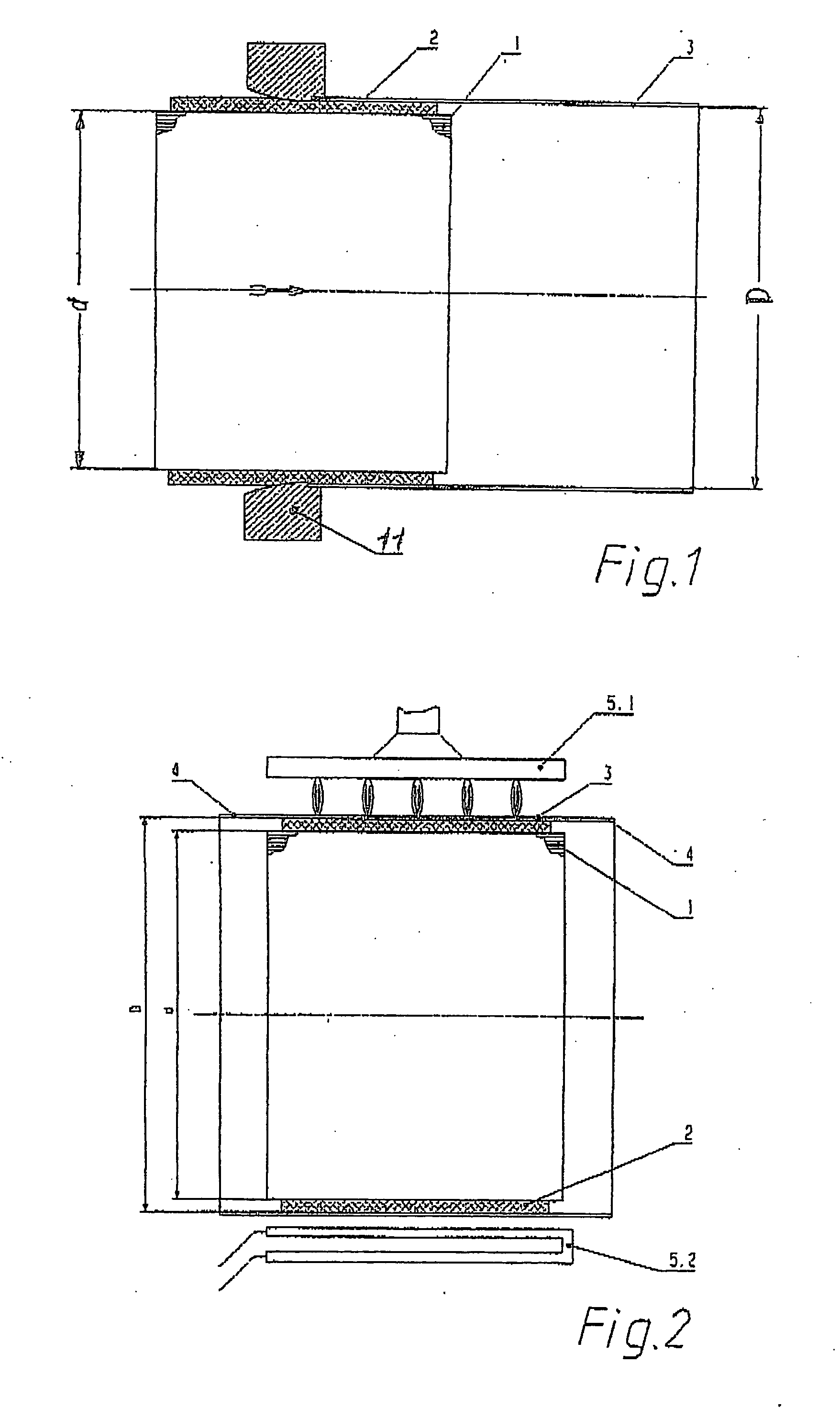
[0021] The sequence of the inventive method is described in a purely schematic fashion on the basis of FIGS. 1 through 4.

[0022] First, a ceramic functional body 1, for example a catalytic converter or diesel exhaust particulate filter, is measured. The diameter d, in particular, is determined in this process. In the case of oval functional bodies, multiple diameters are measured.

[0023] The ceramic functional body 1 is then wrapped with a support mat 2.

[0024] In FIG. 1, the wrapped functional body 1, 2 is inserted in a tubular housing 3 with the aid of a funnel 11. The housing 3 has a significant oversize D. As a result, the support mat 2 is almost completely uncompressed. It experiences no shear forces. The ceramic body 1 and support mat 2 can be precisely positioned within the housing 3. The support mat 2 retains its position, and the ceramic body 1 cannot become canted.

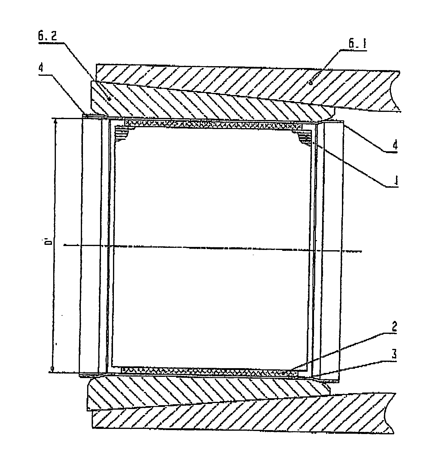
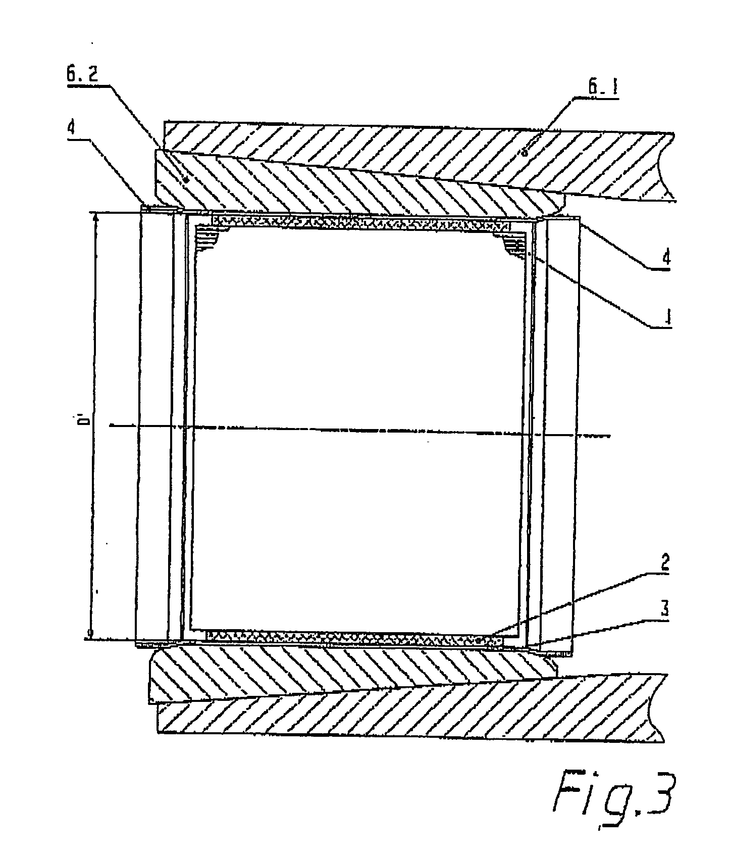
[0025] After the wrapped ceramic body 1, 2 has been slid in, the housing 3 is heated to red or white heat in ...


PUM

PropertyMeasurementUnit
temperaturesaaaaaaaaaa
diameteraaaaaaaaaa

Abstract

A method for inserting a ceramic functional body in a tubular metal housing is disclosed. After the functional body is measured, it is wrapped with a support mat and slid into the housing. This is followed by a heating step of the entire housing. In this state, the housing is then reduced to a dimension that results from the current dimension of the ceramic functional body plus the desired gap dimension in the hot state. Upon cooling, the housing shrinks, and the functional body and the support mat sit correctly in the housing.

Description

[0001] This nonprovisional application claims priority under 35 U.S.C. § 119(a) on German Patent Application No. DE 2005041512, which was filed in Germany on Sep. 1, 2005, and which is herein incorporated by reference. BACKGROUND OF THE INVENTION [0002] 1. Field of the Invention [0003] The present invention relates to a method for inserting a ceramic functional body in a tubular metal housing. The invention further relates to a device thus produced. [0004] 2. Description of the Background Art [0005] Ceramic functional bodies are used as catalysts and as diesel exhaust particulate filters in exhaust systems for motor vehicles with internal combustion engines. The ceramic functional bodies are located in a metal housing, which has a sheet metal jacket, an intake cone, and an outlet cone. In order to be able to compensate for the different coefficients of thermal expansion of metal and ceramic, the ceramic bodies are wrapped in a suitable support mat and inserted in the housing. So tha...

Claims


Application Information

Patent Timeline
Patent Type & Authority Applications(United States)
IPC IPC(8): B01D50/00
CPCF01N3/0211Y02T10/20F01N2450/02F01N3/2853Y02T10/12
Inventor TERRES, FRANK
Owner HEINRICH GILLET GMBH & CO KG
Why Eureka
Try Eureka