
Presence, pattern and weight sensor surface

a sensor surface and pattern technology, applied in the field of presence, pattern and weight sensor surface, can solve the problem that the weight scale cannot measure the weight of many items having different sizes and shapes on the surface independently, and achieve the effect of reducing surface complexity and cos

Inactive Publication Date: 2007-03-01
RF CODE
View PDF18 Cites 161 Cited by
  • Summary
  • Abstract
  • Description
  • Claims
  • Application Information

AI Technical Summary

Benefits of technology

[0019] (4) A surface that provides sensor, temperature, reference and / or other data or input to allow calibration or compensation, for improved accuracy of the surface.
[0021] (6) A surface utilizing the above five features in a manner to minimize surface and tag complexity and cost, by performing at a centralized system level, much of the actual processing of the identification, presence, layout, and / or weight of an item, or items.

Problems solved by technology

However conventional weight scales are unable to measure the weight of many items having different sizes and shapes on a surface independently—without having to individually place them on a scale.

Method used


Image

  • Presence, pattern and weight sensor surface
  • Presence, pattern and weight sensor surface
  • Presence, pattern and weight sensor surface

Examples


Embodiment Construction

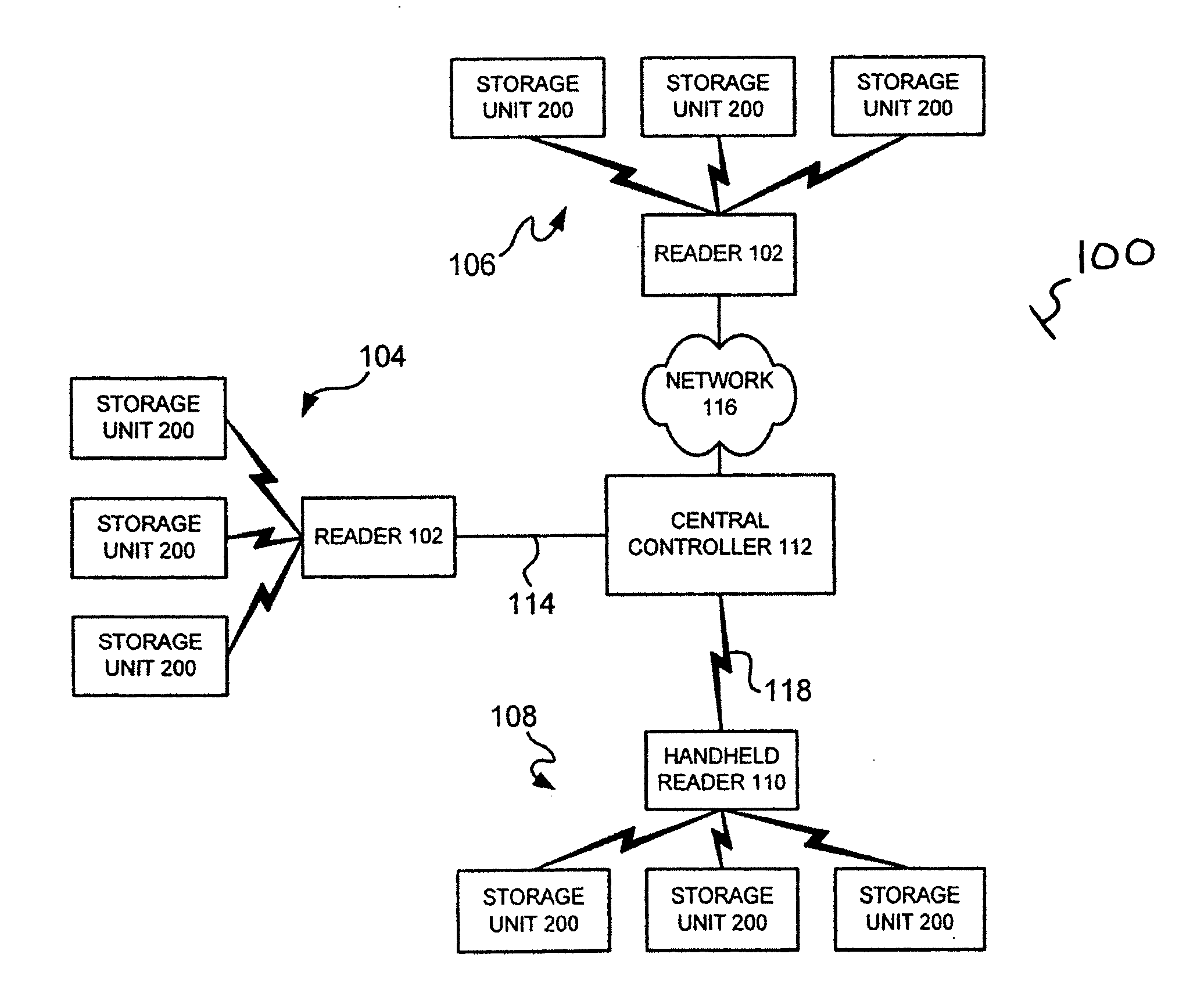
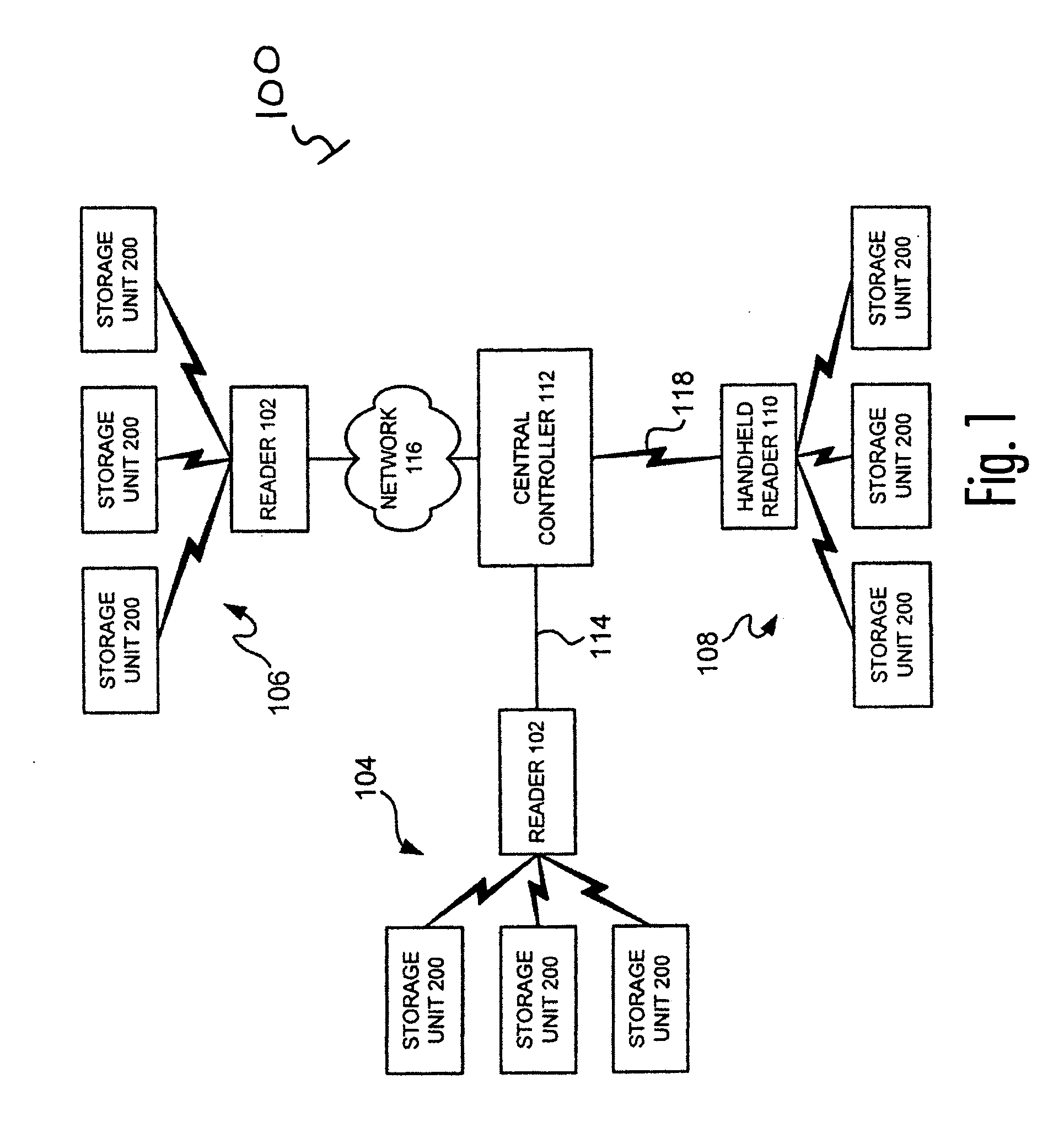
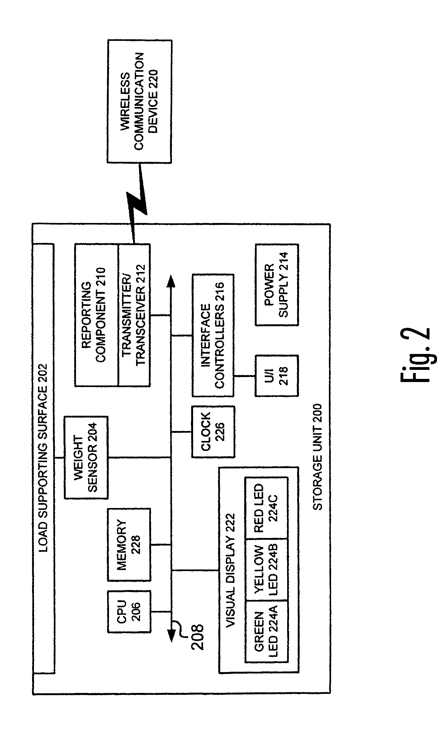
[0045] An inventory control system according to one embodiment of the invention may include one or more storage units and a reader. The reader may receive information transmitted from a storage unit and may use information preloaded in the storage unit to determine an inventory status. Such information may include, for example: Individual Unit Weight, Max Weight (e.g., full inventory), Min Weight (e.g., reorder or restock inventory). The inventory control system may use this information to, for example, provide an automatic stocking request when the reorder point is reached and real-time reports on inventory status.

[0046] Embodiments of the present invention may include a platform (e.g., a mat that may be placed on shelves), a storage rack, a shelf, a floor, a container, a vehicle and / or reusable pallet (e.g., in distribution centers and other locations), collectively referred to as a storage unit. Example applications for the inventory control system may include inventory and prod...


PUM


Abstract

The invention is a system for detecting and reporting the presence and / or weight of inventory items. The system includes a storage unit having a surface for storing inventory items, one or more sensors positioned on the surface, and a reporting unit for receiving and transmitting the first signal. The sensors may detect and send one or more signals to the reporting unit indicative of the presence and / or weight of inventor items on the surface. The reporting unit then transmits this signal to a controller which uses the presence and / or weight data to determine the presence of items on the surface, the weight of items on the surface and / or the pattern of items on the surface. By knowing presence, weight, and / or pattern of items, the controller is better able to determine the identity and quantity of items in the storage unit.

Description

CROSS REFERENCE TO RELATED APPLICATIONS [0001] This application claims the benefit of U.S. Provisional Patent Application No. 60 / 675,343 filed on Apr. 26, 2005, which is hereby incorporated by reference herein. This application is a continuation-in-part and also claims benefit to U.S. patent application Ser. No. 10 / 889,981, filed Jul. 12, 2004, which claims the benefit of U.S. Provisional Application No. 60 / 486,380, filed Jul. 11, 2003 and U.S. Provisional Application No. 60 / 491,406, filed Jul. 31, 2003, all of which are incorporated by reference herein.TECHNICAL FIELD [0002] Embodiments of the invention may relate to systems and methods that monitor the presence, pattern and / or weight of inventory items. BACKGROUND [0003] Automatic weight measuring equipment is well known, including the communication of measured weight data by cable or wireless by radio and other mediums. However, weight-measuring equipment is generally designed to weigh one or more items as a group on a single wei...

Claims


Application Information

Patent Timeline
IPC IPC(8): G06Q10/00
CPCG06Q10/087G06K2017/0048
Inventor UFFORD, ROBERTGLASSER, CHARLESGEIGER, TIMRODGERS, JAMES
Owner RF CODE
Learn More