
Cutting insert with micro-channels

a cutting insert and micro-channel technology, applied in the field of metal cutting, can solve the problems of reduced life of cutting inserts and chemical wear, and achieve the effects of reducing mechanical and thermal load of cutting tools, minimizing contact/friction surfaces, and optimizing cutting edge micro-geometry

Active Publication Date: 2017-08-15
KENNAMETAL INC
View PDF26 Cites 4 Cited by
  • Summary
  • Abstract
  • Description
  • Claims
  • Application Information

AI Technical Summary

Benefits of technology

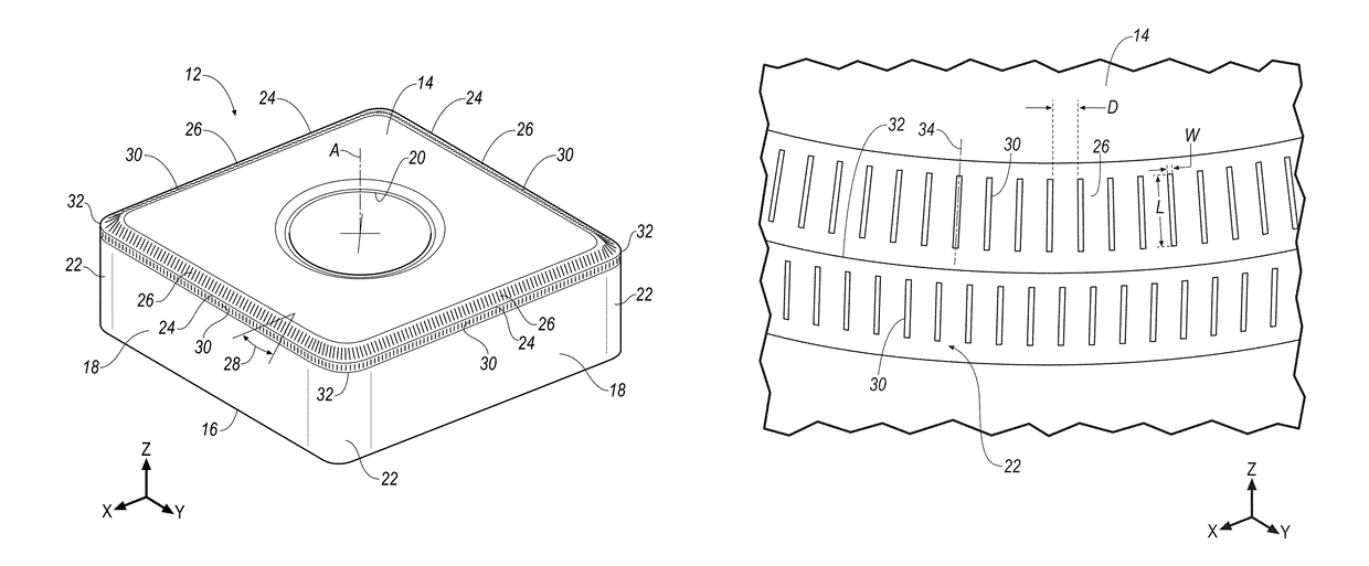
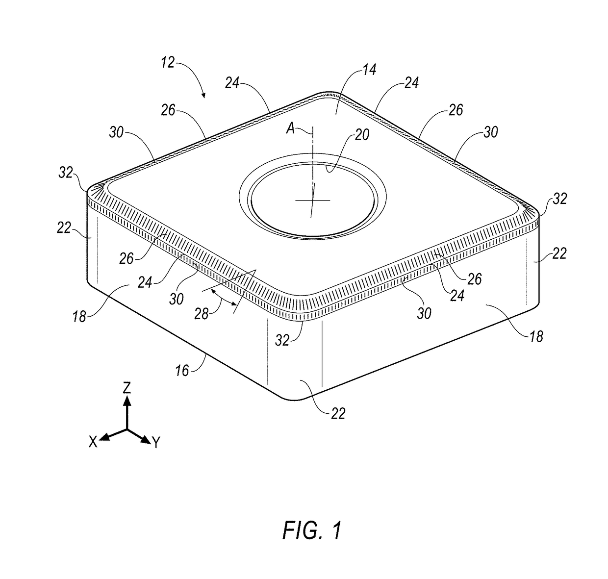
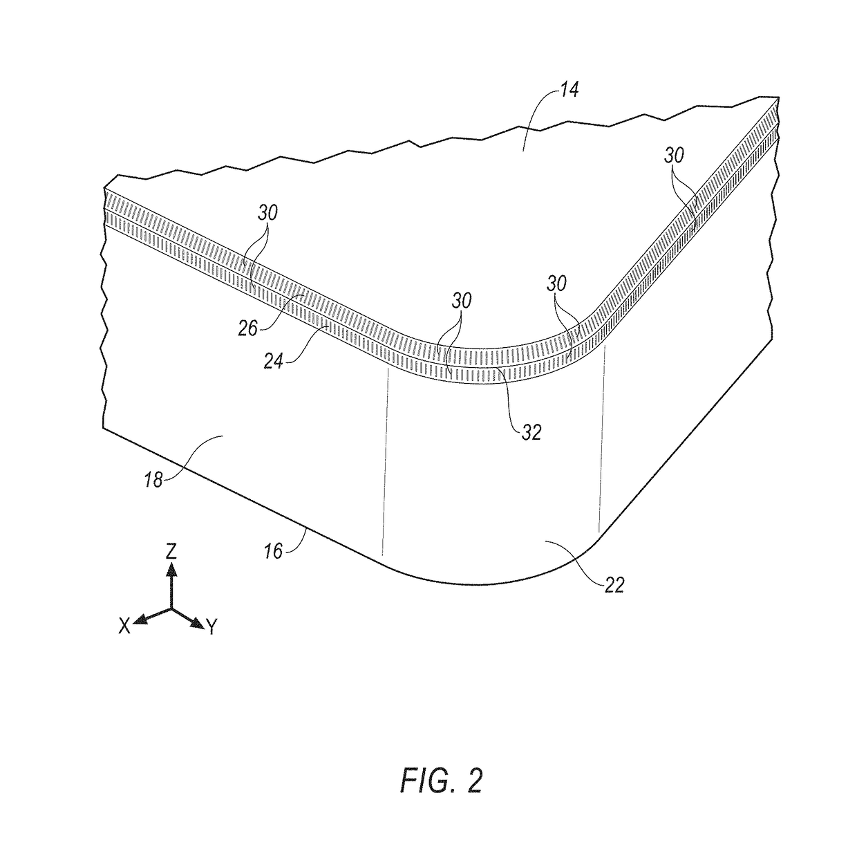
The invention is about improving the performance of milling tools by adding micro-channels to the cutting edge of the tool. These micro-channels help reduce friction between the tool and the workpiece, making it easier for the tool to cut through the material. This results in increased efficiency and durability of the tool, leading to a longer lifespan. The micro-channels can be added using various methods such as laser or mechanical grinding, and can be placed on different areas of the tool that come into contact with the chips formed during machining.

Problems solved by technology

It has been found that the flow of chips against the rake face results in high temperatures leading to chemical wear.
As a result, the life of the cutting insert is reduced.

Method used


Image

  • Cutting insert with micro-channels
  • Cutting insert with micro-channels
  • Cutting insert with micro-channels

Examples


Embodiment Construction

[0017]In the present description of non-limiting embodiments and in the claims, other than in the operating examples or where otherwise indicated, all numbers expressing quantities or characteristics of ingredients and products, processing conditions, and the like are to be understood as being modified in all instances by the term “about”. Accordingly, unless indicated to the contrary, any numerical parameters set forth in the following description and the attached claims are approximations that may vary depending upon the desired properties one seeks to obtain in the apparatus and methods according to the present disclosure. At the very least, and not as an attempt to limit the application of the doctrine of equivalents to the scope of the claims, each numerical parameter should at least be construed in light of the number of reported significant digits and by applying ordinary rounding techniques.

[0018]Any patent, publication, or other disclosure material, in whole or in part, tha...


PUM

PropertyMeasurementUnit
widthaaaaaaaaaa
widthaaaaaaaaaa
depthaaaaaaaaaa

Abstract

A cutting insert includes a body having an upper face, a lower face, a plurality of planar flank faces joining the upper and lower faces, and a plurality of curved flank faces joining the plurality of flank faces. A T-land is formed at a downward sloping angle with respect to the upper face. A cutting edge is formed at an intersection of a respective flank face and the T-land. A curved cutting edge is formed at an intersection of a respective curved flank face and the T-land. A micro-channel is formed in one of the flank faces, the curved flank faces and the T-land and proximate one of the cutting edge and the curved cutting edge.

Description

BACKGROUND OF THE INVENTION[0001]It is a continuing goal in the metal cutting industry to provide metal cutting inserts with an adopted cutting edge to the application that conserve its original geometry as long as possible. Chips (or swarf) is formed during a metal cutting operation. It has been found that the flow of chips against the rake face results in high temperatures leading to chemical wear. Crater wear can be formed proximate to the cutting edge, as shown in FIG. 9. As a result, the life of the cutting insert is reduced.[0002]Another goal is to control the chip form. Short chips are preferred. Adequate rake face geometry would support chip forming and chip breakages.SUMMARY OF THE INVENTION[0003]The purpose of the invention is to minimize contact / friction surface, optimize cutting edge micro-geometry as well as chip forming, chip generation and chip breakage. This is accomplished by providing three-dimensional (3-D) elements or shapes on an area of the insert that is in co...

Claims


Application Information

Patent Timeline
Patent Type & Authority Patents(United States)
IPC IPC(8): B23B27/00B23B27/14
CPCB23B27/005B23B27/145B23B2200/086B23B2200/128B23B2200/242B23B2200/325B23B2200/3645B23B2226/125B23B2226/18B23B2226/315B23B2250/12Y10T29/49996Y10T407/24
Inventor KONDAMEEDI, NAVEENBEN AMOR, RAOUF
Owner KENNAMETAL INC
Learn More