Method and an apparatus for the creation of a tangible item, such as a tool and/or a part, and a tangible item

a tangible item and method technology, applied in the field of tangible items creation methods and apparatuses, can solve the problems of poor overall performance, difficult to cause a large number of sectional members to properly and cooperatively produce a large tool, variable and often unequal amount of compression within, etc., to achieve cost-efficient and relatively accurate manner, varying size and shape, the effect of varying the size and shap

Inactive Publication Date: 2007-03-08
EDMOND DANTES HLDG LLC
View PDF61 Cites 0 Cited by
  • Summary
  • Abstract
  • Description
  • Claims
  • Application Information

AI Technical Summary

Benefits of technology

[0007] It is a first non-limiting advantage of the present invention to provide a method and an apparatus for the creation of a tangible item.
[0008] It is a second non-limiting advantage of the present invention to provide a method and an apparatus for the creation of a tangible item which overcomes many, if not all, of the above-delineated drawbacks associated with existing lamination processes.
[0009] It is a third non-limiting advantage of the present invention to provide a method and an apparatus for the creation of a tangible item which may have a greatly varying size and shape.
[0010] It is a fourth non-limiting advantage of the present invention to provide a method and an apparatus for the creation of a tangible item which may have a greatly varying size and shape and which allows for the use of separately designed and constructed sectional members to cooperatively form the tangible item in a cost efficient and relatively accurate manner.
[0011] It is a fifth non-limiting advantage of the present invention to provide a new and novel tangible item made by a new and novel process which allows for the creation of tangible item by the use of a plurality of sectional members.
[0012] According to a first non-limiting aspect of the present invention, an apparatus is provided for creating a tangible item from the use of first and second sectional members. Particularly, the apparatus includes a first portion which selectively forms a first protuberance within the first sectional member, the first protuberance having a certain first diameter, the first portion further forming a second protuberance within the second sectional member, the second protuberance having a second diameter which is smaller than the certain first diameter; and a second portion which causes the second protuberance to be selectively nestled and to frictionally fit within the first protuberance.

Problems solved by technology

By way of example and without limitation, it is oftentimes difficult to cause a large number of sectional members to properly and cooperatively produce a large tool.
Such difficulty lies in the variable and often unequal amount of compression which occurs within and / or between each of the sectional members (e.g., as the various sectional members are compressed as they are attached together to form the desired tool or mold).
Such difficulty further lies in the variable and often unequal amount and type of twist or physical distortion which occurs in some or all of the coupled sectional members, and the structural deformity occurring due to the technique used to actually and physically align the sectional members prior to joining them in a cooperative fashion (i.e., oftentimes it is very difficult to properly align each of the sectional members in the required fashion and such misalignment may cause malfunction, poor overall performance, and actually cause and / or contribute to a decrease in the overall integrity or strength of the cooperative connection required to create the. desired tool, die, or mold).
Further, due to the large number of sectional members, small alignment errors occurring in the joining of some or all of these members (e.g., misalignments which may be caused by structural imperfections within or upon the various sectional members) as well as other errors, caused by such phenomena as compression and distortion, accumulates or compounds, thereby causing a tool to be produced which is undesirable and which is of a physical form which is undesirable (i.e., has undesirable spatial dimensions).
While these approaches do allow sectional members to be selectively joined, they do not fully address the previously described difficulty.
That is, each of these techniques increase the cost and complexity of the overall tool building process and increases the potential for causing further misalignment or damage to the overall constructed tool.
Additionally, the adhesive normally has to be at least partially removed and the tool “cleaned” after it is constructed, thereby further increasing the complexity of the overall tool building process and these “joining strategies” do not precisely provide a consistent connection having consistent geometric and spatial attributes (e.g. one welded or adhesive connection may be “thicker” than another or have a non-uniform thickness), thereby further contributing to undesired misalignment.
Further, these connections (especially an adhesive connection) may have spatial attributes which change over time (e.g., as the adhesive “dries out”, the connection may become non-uniform in thickness and actually cease to function, thereby causing the tool, die, or mold to fail).
Hence, these above-delineated drawbacks in combination with the lack of a technique or strategy to adequately address these drawbacks has caused the use of the lamination process to be practically used to build smaller tools and to be of rather limited use in building other types of complex tangible items (e.g., parts having a greatly varying or complex shape).

Method used


Image

  • Method and an apparatus for the creation of a tangible item, such as a tool and/or a part, and a tangible item
  • Method and an apparatus for the creation of a tangible item, such as a tool and/or a part, and a tangible item
  • Method and an apparatus for the creation of a tangible item, such as a tool and/or a part, and a tangible item

Examples


Embodiment Construction

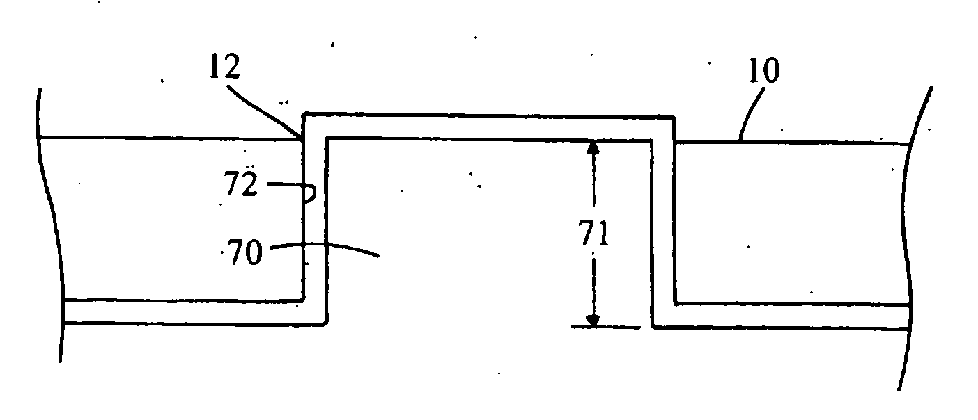
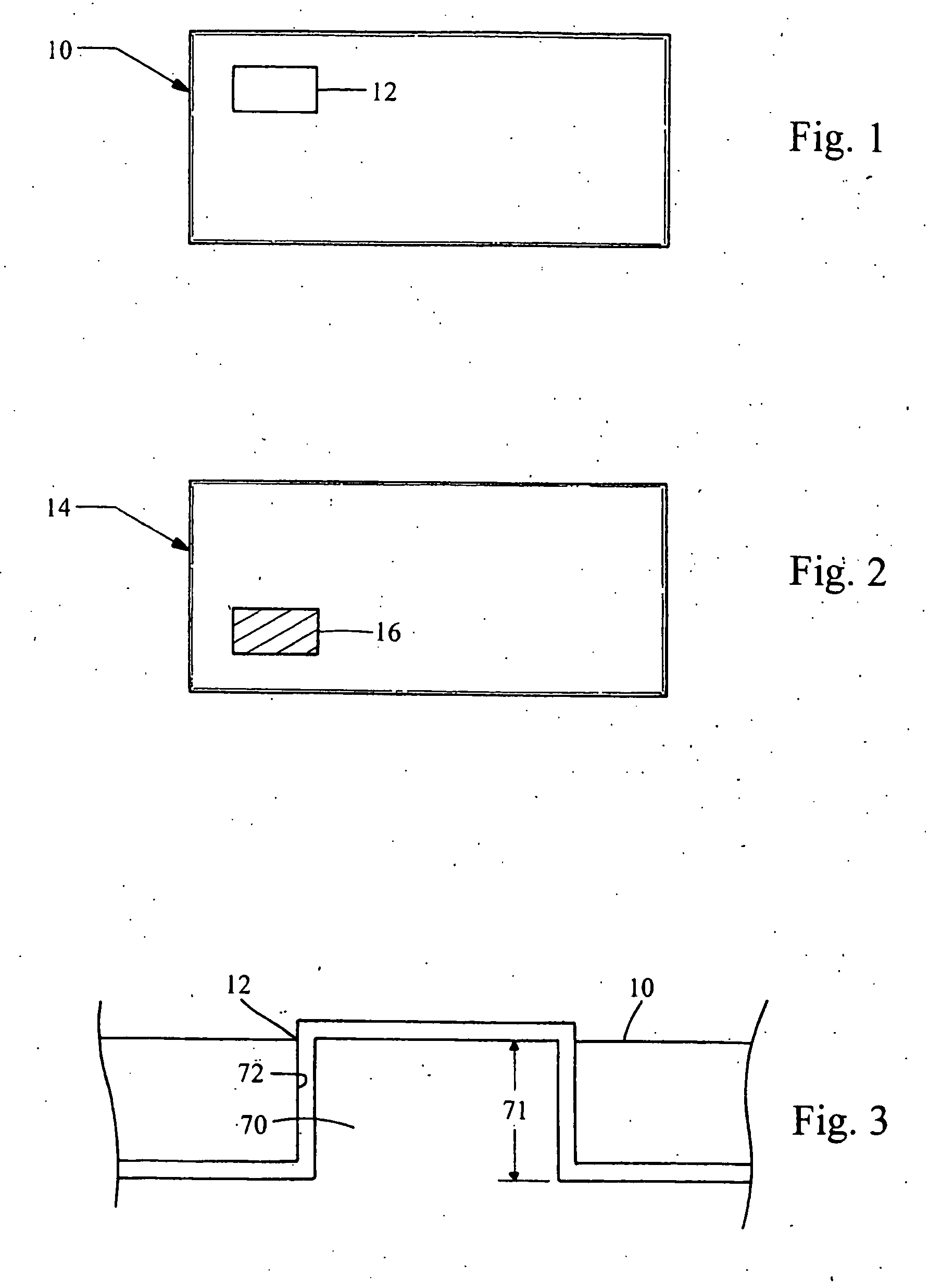
[0029] Referring now to FIG. 1, there is shown a sectional member 10 which is made in accordance with the teachings of the preferred embodiment of the invention. Particularly, it should be appreciated that sectional member 10 may be of substantially any desired shape and size (i.e., of any desired geometric configuration) and that nothing in this description is meant or should be construed to limit that size, shape, or geometric configuration of the sectional member 10 in any manner whatsoever. The term “sectional member” may mean a tangible item which has spatial properties (e.g., size and shape) derived from a model of an overall desired tangible item to be produced and which is adapted to be selectively coupled to another sectional member to cooperatively form the desired overall tangible item. Such sectional member may be made by a similar process to that which is shown and described within the '742 Patent.

[0030] According to the teachings of the present invention and as perhap...


PUM

PropertyMeasurementUnit
cylindrical shapeaaaaaaaaaa
dimensionaaaaaaaaaa
perimeteraaaaaaaaaa

Abstract

An apparatus and a methodology 200, 350 for producing a tangible item 120 by the use of a plurality of sectional members, such as sectional members 10 and 14. In one embodiment, each sectional member 14 includes a protuberance 16 and these protuberances are selectively nestled to allow the various sectional members 14 to be connected and to cooperatively form a tangible item, such as tangible item 120. In an alternate embodiment of the invention, a first sectional member includes an opening 12 which receives a protuberance 70 from another sectional member. Other sectional members may thereafter be coupled to this assembly by the use of nestled protuberances, thereby allowing the coupled sectional members to cooperatively create a tangible item.

Description

CROSS-REFERENCE TO RELATED APPLICATIONS [0001] This is a continuation of copending application Ser. No. 10 / 794,011 filed on Mar. 5, 2004.FIELD OF THE INVENTION [0002] The present invention generally relates to a method and an apparatus for the creation of a tangible item, such as a tool and / or a part and more particularly, by way of example and without limitation, to a method and an apparatus which allows such a tangible item to be made by the use of separately formed members which may be selectively joined to cooperatively form the desired tangible item. The present invention also relates to a new and novel tangible item created by a new and novel joining process or methodology. BACKGROUND OF THE INVENTION [0003] It is known that a tool, such as a mold or a die, may be produced by selectively attaching sections or members in a manner which allows these sections or members to cooperatively form the desired mold or die (e.g., by the use of an adhesive). One such process, which may be...

Claims


Application Information

Patent Timeline
Patent Type & Authority Applications(United States)
IPC IPC(8): B23P25/00B23P11/00F16B1/00
CPCB23P15/246B23P2700/12Y10T29/49885Y10T29/49924Y10T29/49908Y10T403/7094F16B2200/30
Inventor MANUEL, MARK
Owner EDMOND DANTES HLDG LLC
Why Eureka
Try Eureka