
Lawn mower

a mower and blade technology, applied in the field of lawn mowers, can solve the problems of operator needs and operator operating position, and achieve the effect of reducing the risk of the mower deck falling back to its original position and minimizing the tip forward

Active Publication Date: 2007-03-08
HUSQVARNA AB
View PDF10 Cites 5 Cited by
  • Summary
  • Abstract
  • Description
  • Claims
  • Application Information

AI Technical Summary

Benefits of technology

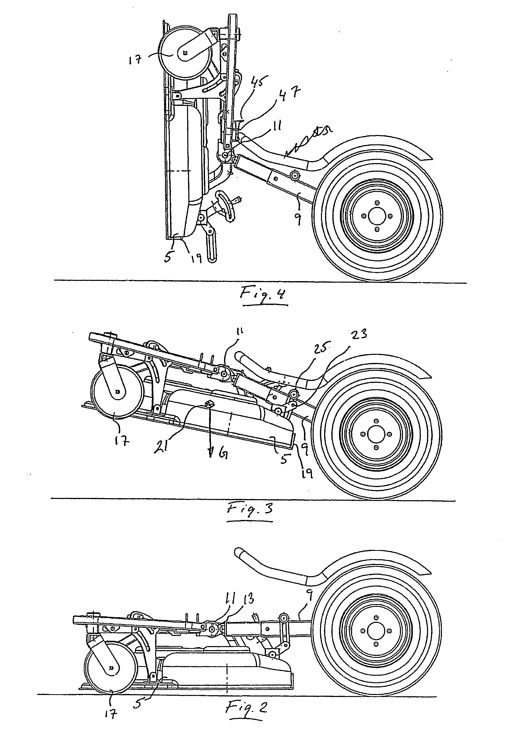
[0008] Since the centre of gravity of the mower deck is located in front of the pivot axis, with respect to the forward direction of the lawn mower, an important advantage is achieved. What is happening is that the mower deck will perform a pivotal motion so it approaches the support arms from below when the mower deck is lifted to the upper position. This pivotal motion is obtained automatically under the influence of the weight of the mower deck, due to the centre of gravity location with respect to the pivot axis, and continues until the mower deck abuts against the underside of the support arms. Thus, the operator does not need to hold the rear edge of the mower deck with one hand to prevent the mower deck from falling down.
[0009] Preferably, the lawn mower comprises a locking mechanism for locking a rear edge of the mower deck to the support arm, at a point which is located behind the pivot axis, with respect to the forward direction of the lawn mower. Hereby, the locking mechanism will not be subjected to the weight of the lawn mower when the mower deck is put in the upper position. Thus, unlocking is simplified.
[0011] Preferably, the centre of gravity of the mower deck is located just in front of the pivot axis with respect to the forward direction of the lawn mower. Hereby, the risk that the lawn mower becomes unbalanced and tip forward is minimized.
[0012] Suitably, the underside of the mower deck is directed substantially forwardly when the mower deck is in the second position. Hereby, the underside is readily accessible to the operator.
[0013] Preferably, the plane of the mower deck has passed the vertical line when the mower deck is in the second position. Hereby, the risk that the mower deck falls back to its original position is reduced.

Problems solved by technology

However, a disadvantage with this mower deck is that the operator needs to hold the rear edge of the mower deck with one hand while the other hand unlocks the locking mechanism.
This puts the operator in an operating position which is disadvantageous from an ergonomic point of view.

Method used


Image

  • Lawn mower
  • Lawn mower
  • Lawn mower

Examples


Embodiment Construction

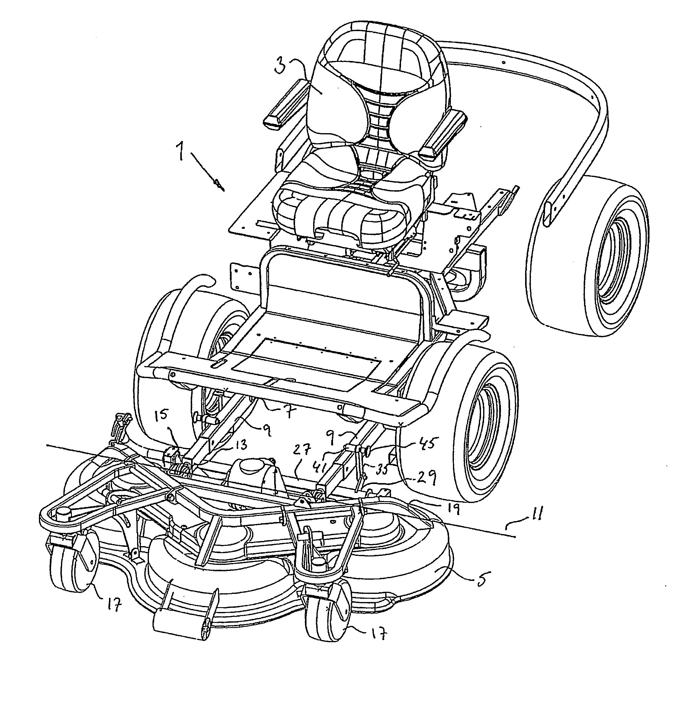
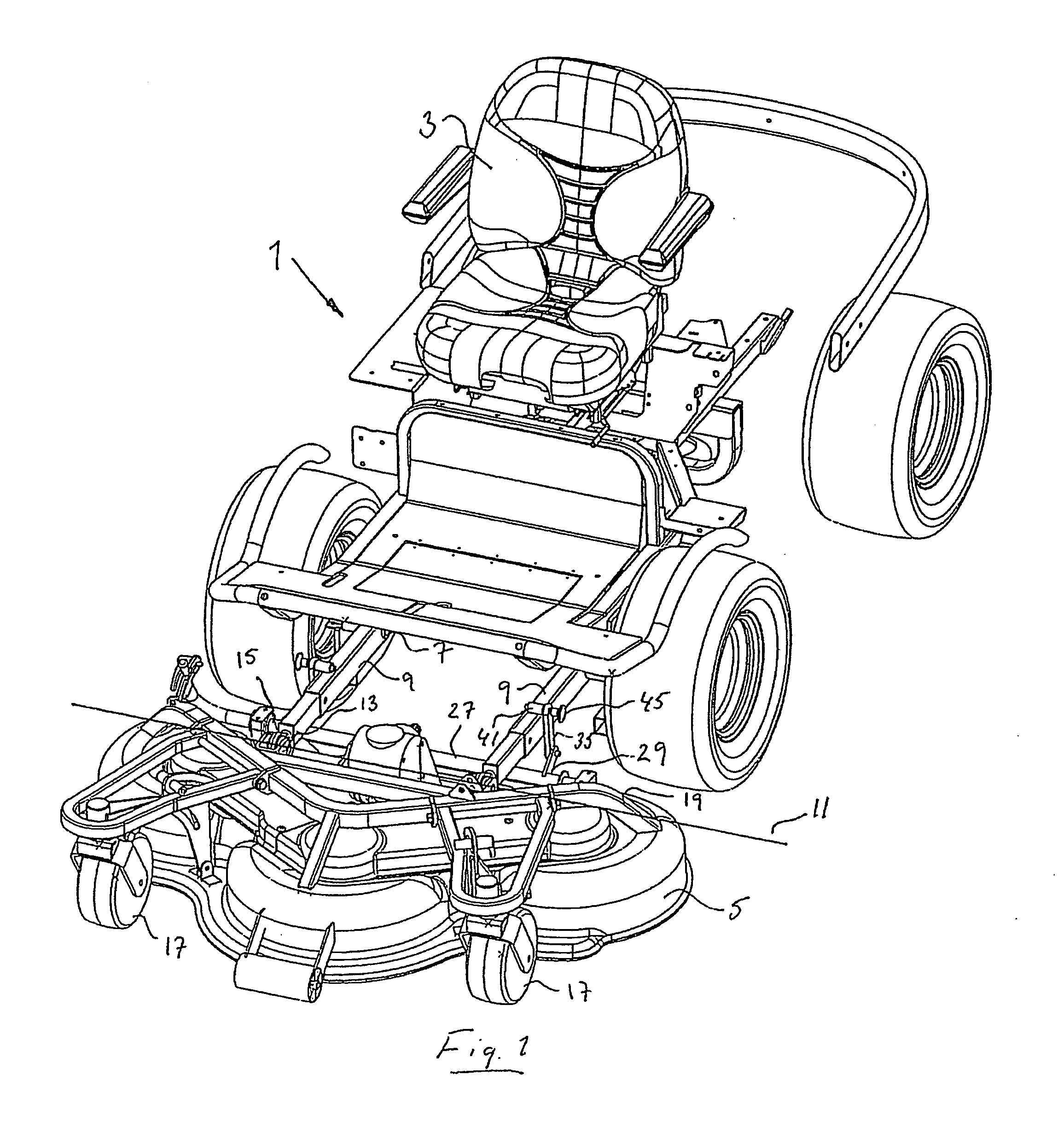
[0019]FIG. 1 shows a lawn mower 1 according to the present invention. The lawn mower comprises a seat 3 for an operator to sit on when manoeuvring the lawnmower 1. Steering wheel, brake pedal, throttle pedal as well as other handles, knobs and pedals suitable for its operation have been omitted for the sake of clarity. The lawn mower 1 further comprises a front mounted mower deck 5 which is connected to the chassis 7 of the lawn mower by means of first and second support arms 9. The term mower deck 5 is intended to mean the whole unit which is connected to the support arms in front of the lawn mower, i.e. including the whole casing with pivot wheels, cutting knifes, cutting height adjusting equipment and so on.

[0020] The support arms 9 are vertically adjustable by means of a not shown hydraulic cylinder. This means that the mower deck 5 can be lifted from a lower cutting position to an upper transport position. The mower deck 5 can also be tilted about a horizontal pivot axis 11 wi...


PUM


Abstract

The present invention relates to a lawn mower (1), comprising a chassis (7), a front mounted mower deck (5), and at least one support arm (9) connecting the mower deck (5) with the chassis (7), wherein the support arm (9) is movable with respect to the chassis (7) for lifting the mower deck (5) from a lower position to an upper position, in which upper position the mower deck (5) is tiltable about a horizontal pivot axis (11) with respect to the support arm (9) without interfering with the ground, from a first position in which an underside of the mower deck (5) is directed downwardly, to a second position in which the underside of the mower deck (5) is accessible to an operator standing in front of the lawn mower (1). The lawn mower is characterised in that the centre of gravity (21) of the mower deck (5) is located in front of the pivot axis (11), with respect to the forward direction of the lawn mower (1), when the mower deck (5) is lifted to the upper position.

Description

FIELD OF THE INVENTION [0001] The present invention relates to a lawn mower in accordance with the preamble of claim 1. BACKGROUND OF THE INVENTION [0002] Lawn mowers with front mounted mower decks regularly require service and maintenance, e.g. grass removing, cleaning and sharpening of the cutting knifes so as to function properly. When the lawn mower is positioned on the ground, the part of the mower deck to be serviced, i.e. the underside is normally inaccessible to an operator. A common solution to this problem is to make the mower deck tiltable so that an operator can get access to the underside. RELATED ART [0003] A related art lawn mower comprises a chassis, a front mounted mower deck and support arms connecting the mower deck with the chassis. The support arms are movable with respect to the chassis for lifting the mower deck from a lower position to an upper position, in which upper position the mower deck is tiltable about a horizontal pivot axis with respect to the suppo...

Claims


Application Information

Patent Timeline
Patent Type & Authority Applications(United States)
IPC IPC(8): A01D34/00
CPCA01D34/662A01D2101/00A01D2034/645Y10S56/22
Inventor LILLIESTIELKE, FREDRIKMEJEGARD, PETERAXELSSON, MATS
Owner HUSQVARNA AB
Learn More