Method for molding three-dimensional foam products using a continuous forming apparatus

a technology of continuous forming and foam products, which is applied in the direction of cheese production, butter production, textiles and papermaking, etc., can solve the problems of limiting the practical size of the slider-bed supported forming apparatus for foam materials, the foaming pressure is not constant along the length of the machine, and the machine is extremely expensive, so as to achieve the effect of less expensive, efficient production of a range of simulated materials, and low cos

Active Publication Date: 2007-03-08
CENTURY BOARD CORP +1
View PDF96 Cites 36 Cited by
  • Summary
  • Abstract
  • Description
  • Claims
  • Application Information

AI Technical Summary

Benefits of technology

[0015] The continuous forming apparatus may also include a drive mechanism for imparting motion to the first endless belt, the first plurality of cleats, and the second plurality of cleats. The drive mechanism may be connected to the first endless belt, the first plurality of cleats, and the second plurality of cleats so that they move at the same speed. By moving at the same speed, the first plurality of cleats and the second plurality of cleats may grip the first endless belt to provide constant support to the first endless belt as a molded foam product is cured and to reduce the friction resulting from moving the first endless belt.
[0024] The frames also permit a transverse gap to be disposed between the first plurality of cleats and the second plurality of cleats when the first plurality of cleats supports the first endless belt for molding foam material. The gap is closed by one or more of the endless belts to prevent the foaming material from exiting the mold cavity. Additionally, leaving a small gap between the first plurality of cleats and the second plurality of cleats may help to prevent the first plurality of cleats from binding with the second plurality of cleats. The gap may range from about an inch to almost abutting but preferably is about 0.1 inches. Of course, the first plurality of cleats may abut the second plurality of cleats when the first plurality of cleats supports the first endless belt for molding foam material.

Problems solved by technology

However, these machines are extremely expensive and adjacent mold sections must fit together precisely to prevent material from oozing and binding between mold sections.
The wider the product and longer the forming apparatus, the greater the friction that the drive mechanism must overcome, which limits the practical size of a slider-bed supported forming apparatus for foam materials.
Roller-supported mold belts minimize belt-to-bed friction, but the belts are unsupported in the spans' between adjacent rollers, allowing the belt to deflect outward.
The roller-bed supported belts virtually eliminate the friction associated with slider-beds, but the foaming pressure on the belt is not supported between individual rollers allowing the belts to intermittently gap open as they travel.
However, the foaming pressure is not constant along the length of the machine, especially for thermoset foams.
Additionally, air film lubrication is limited to smaller parts with low foaming pressures in order to avoid using excessively high-pressure air.

Method used


Image

  • Method for molding three-dimensional foam products using a continuous forming apparatus
  • Method for molding three-dimensional foam products using a continuous forming apparatus
  • Method for molding three-dimensional foam products using a continuous forming apparatus

Examples


Embodiment Construction

[0044] The presently preferred embodiments of the present invention will be best understood by reference to the drawings, wherein like parts are designated by like numerals throughout. It will be readily understood that the components of the present invention, as generally described and illustrated in the figures herein, could be arranged and designed in a wide variety of different configurations. Thus, the following more detailed description of the embodiments of the continuous forming apparatus of the present invention, as represented in FIGS. 1 through 18, is not intended to limit the scope of the invention, as claimed, but is merely representative of presently preferred embodiments of the invention.

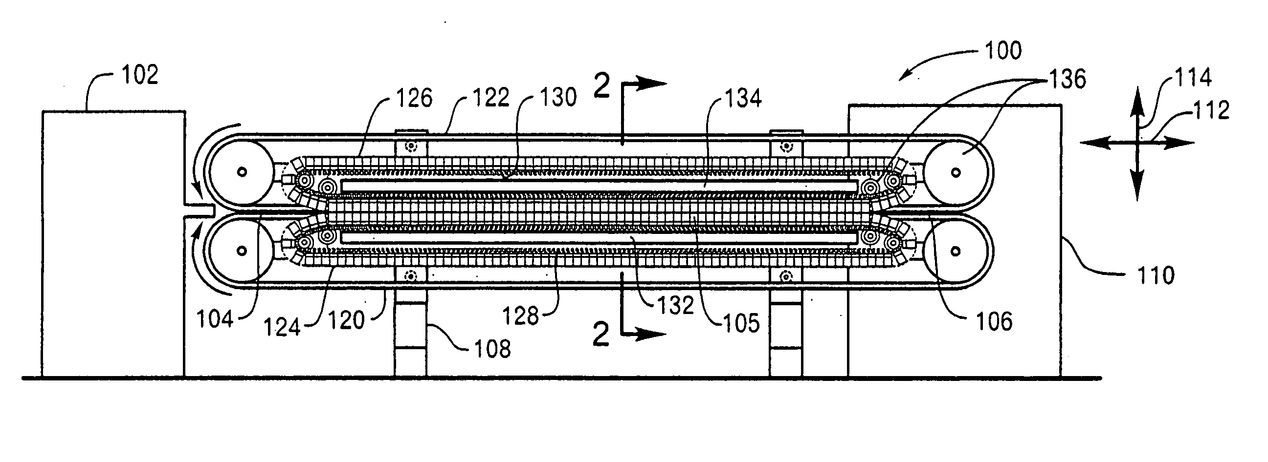
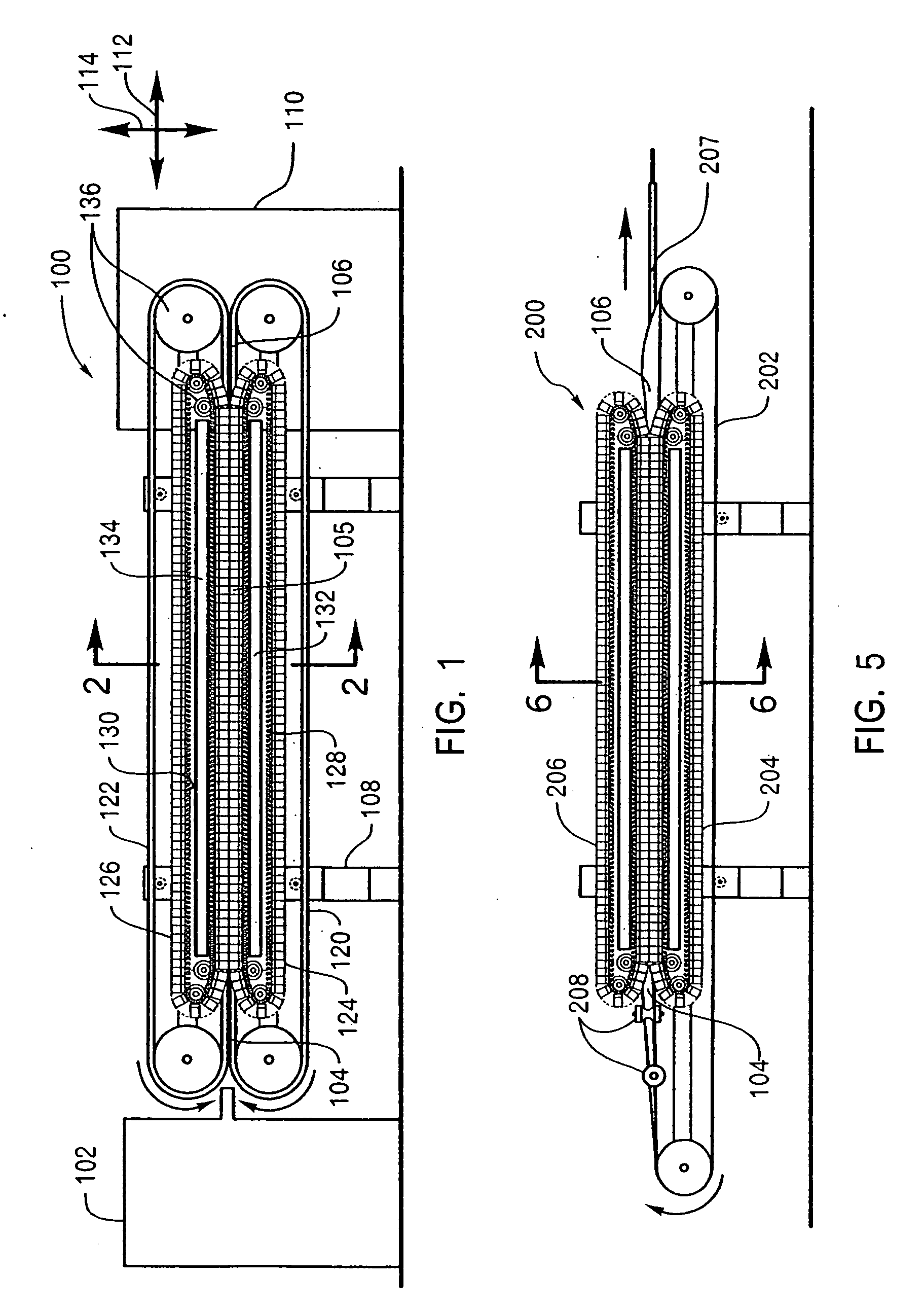
[0045]FIG. 1 is an elevated side view of a continuous forming apparatus 100 according to the invention. The continuous forming apparatus 100 receives foaming material from a feeder machine 102 in an input end 104, such as an extrusion machine or other feeding machine known in the art...


PUM

PropertyMeasurementUnit
areaaaaaaaaaaa
moldingaaaaaaaaaa
shapesaaaaaaaaaa

Abstract

A continuous forming apparatus for molding foam material into foam products that includes a first endless belt and a second endless belt that cooperates with the first endless belt to mold the foam material. The continuous forming apparatus may also include a first plurality of cleats and a second plurality of cleats opposed to the first plurality of cleats that support the first endless belt and the second endless belt respectively. The first plurality of cleats may include a three-dimensional abutment surface that provides transverse and lateral support to the first endless belt. Additionally, the continuous forming apparatus may include a first frame disposed to support the first plurality of cleats, a second frame disposed to support the second plurality of cleats, and a drive mechanism for imparting motion to the first endless belt, the second endless belt, the first plurality of cleats, and the second plurality of cleats.

Description

CROSS-REFERENCE TO RELATED APPLICATIONS [0001] The present application is a continuation of U.S. patent application Ser. No. 11 / 165,071, filed Jun. 23, 2005, which claims priority benefit under 35 U.S.C. § 119(e) from U.S. Provisional Application No. 60 / 585,420, filed Jun. 24, 2004. The present application incorporates both documents herein by reference.BACKGROUND OF THE INVENTION [0002] The present invention relates generally to continuous forming apparatus and methods for forming foam materials into three-dimensional shapes. Generally, the production of three-dimensional products made from a foam material requires a mold that can both define the three-dimensional shape and contain any pressure exerted by the foam material until the product is rigid enough to be removed from the mold. [0003] To accomplish these requirements, currently available production apparatus for continuous production include endless flexible mold belts and chain-mounted rigid mold sections. Endless flexible ...

Claims


Application Information

Patent Timeline
Patent Type & Authority Applications(United States)
IPC IPC(8): B29C67/20B29C43/22B29C44/30
CPCB29C39/16B29C44/306B29C35/0277B29C37/0075B29C44/585B29K2105/04B29L2007/002
Inventor TAYLOR, ZACHARY R.
Owner CENTURY BOARD CORP
Why Eureka
Try Eureka