Fluid pump and electric motor, and manufacturing method for the same

Inactive Publication Date: 2007-03-08
DENSO CORP
View PDF13 Cites 42 Cited by
  • Summary
  • Abstract
  • Description
  • Claims
  • Application Information

AI Technical Summary

Benefits of technology

[0005] In view of the foregoing and other problems, it is an object of the present invention to produce a fuel pump including a rotator and a stationary part defining a fuel passage, in whic

Problems solved by technology

Furthermore, the portion defining the injection port mark on the permanent magnet is apt to be rust due to being submerged in fuel.
However, when the through hole of the permanent magnet is deformed due to aging or the like, bond strength between the permanent magnet an

Method used


Image

  • Fluid pump and electric motor, and manufacturing method for the same
  • Fluid pump and electric motor, and manufacturing method for the same
  • Fluid pump and electric motor, and manufacturing method for the same

Examples


first embodiment

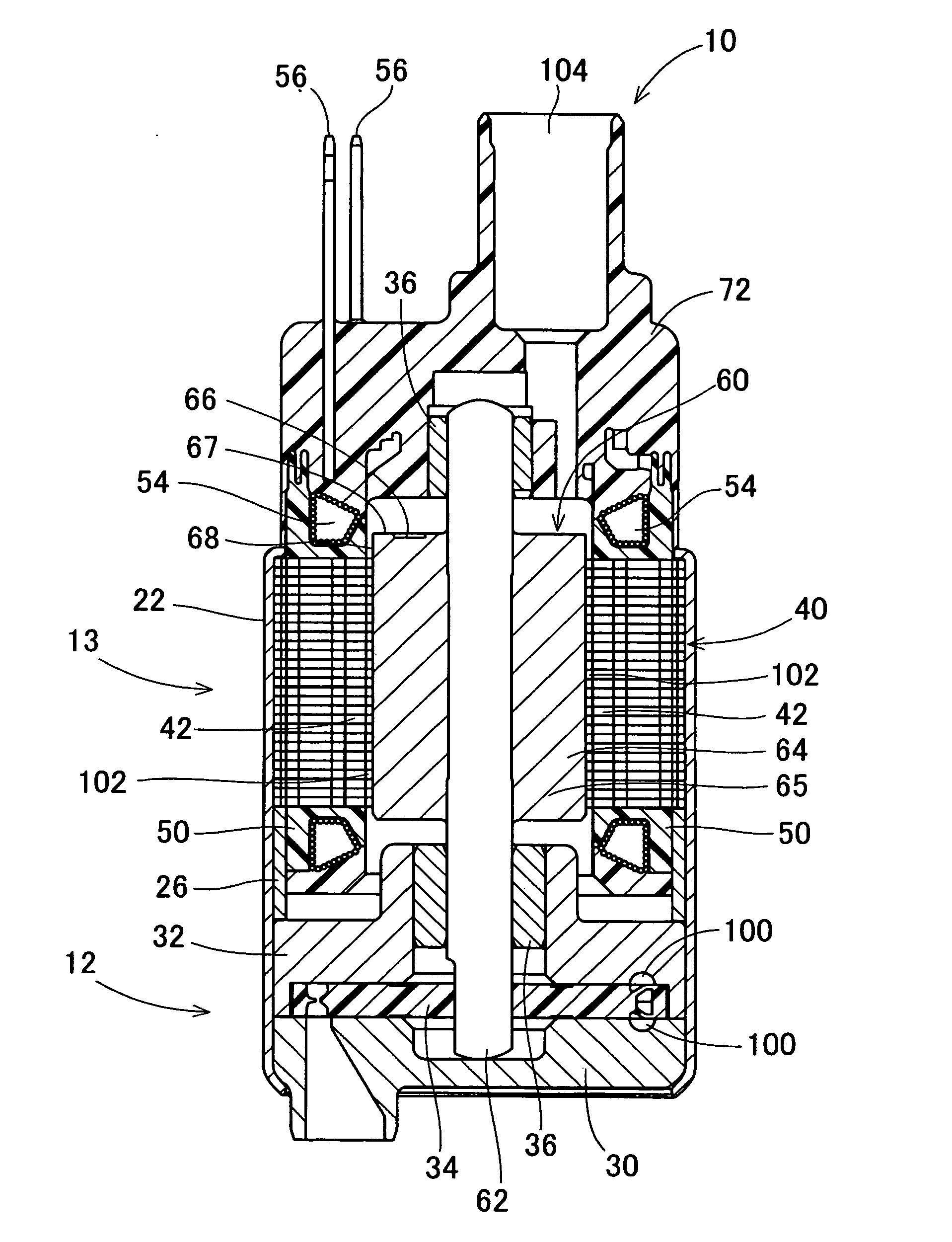
[0027] As shown in FIG. 1, a fuel pump 10 of this embodiment is an in-tank turbine pump, for example. The fuel pump 10 is provided in a fuel tank of a motorcycle with an engine size of 150 cc, for example. The fuel pump 10 includes a pump portion 12 and a motor portion 13. The motor portion 13 rotates the pump portion 12.

[0028] The housing 22 accommodates the pump portion 12 and the motor portion 13. The pump portion 12 includes pump cases 30, 32 that rotatably accommodate an impeller 34. The pump cases 30, 32 and the impeller 34 define pump passages 100 thereamong. The pump passages 100 are in substantially C-shapes.

[0029] The motor portion 13 serves as a brushless motor that includes a stator core 40, bobbins 50, coils 54, and a rotator 60. The stator core 40 serves as a stationary part. The stator core 40 is formed by crimping axially stacked magnetic steel plates to each other. The stator core 40 is provided with six teeth 42 protruding toward the center of the motor portion 1...

second embodiment

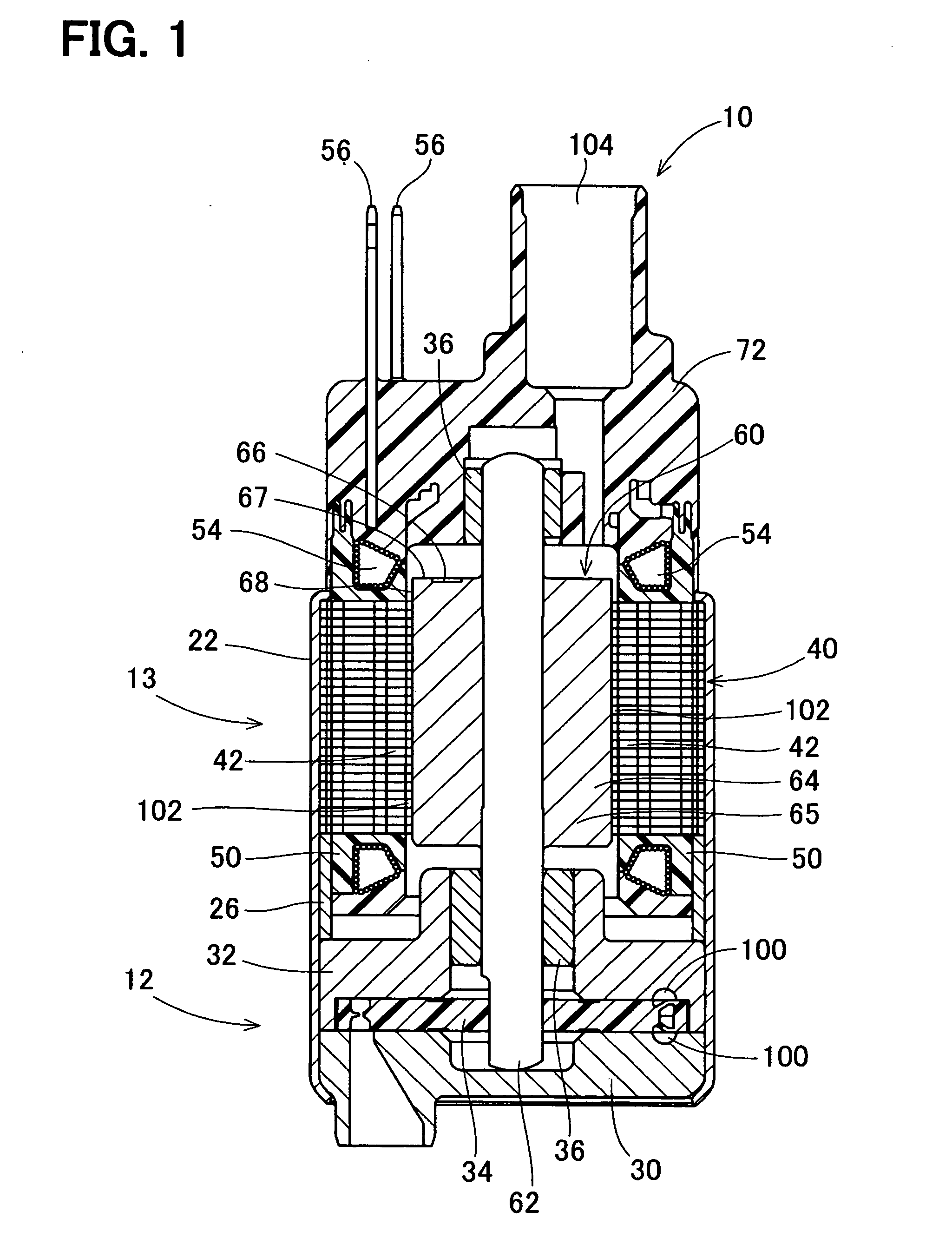
[0044] As shown in FIG. 4, a rotator 260 of a fuel pump of the second embodiment includes the shaft 62, a rotational core 269, and a permanent magnet 264. The permanent magnet 264 is a resin magnet that is formed by injection molding a composite material containing thermoplastic resin such as PPS and magnetic powder such as NeFeB. The permanent magnet 264 is shaped to be in a substantially cylindrical shape, and is fixed to the outer circumferential periphery of the rotational core 269. The permanent magnet 264 has eight magnetic poles arranged with respect to the rotative direction, similarly to the permanent magnet 64 in the first embodiment.

[0045] The pressurized fuel is press-fed toward an outlet port through a fuel passage defined between the inner circumferential periphery of a stator core and an outer circumferential end 268 of the permanent magnet 264, and the fuel is discharged toward the engine through the outlet port, similarly to the fuel pump 10 in the first embodiment...

third embodiment

[0047] As shown in FIG. 5, a fuel pump 310 includes a pump portion 320, a motor portion 330, and an end support cover 314. The motor portion 330 rotates an impeller 326 of the pump portion 320. The housing 312 surrounds the outer circumferential peripheries of the pump portion 320 and the motor portion 330. The housing 312 is a common housing of the pump portion 320 and the motor portion 330. The end support cover 314 covers the motor portion 330 on the opposite side of the pump portion 320. The end support cover 314 defines an outlet port 306 of fuel.

[0048] The pump portion 320 is a Wesco pump, for example. The pump portion 320 includes a pump cover 322, a pump casing 324, and the impeller 326. The pump cover 322 and the pump casing 324 are casing member that rotatably accommodates the impeller 326. The pump cover 322 and the impeller 326 define a pump passage 302 therebetween. The pump casing 324 and the impeller 326 define the pump passage 302 therebetween. The pump passages 302...


PUM


Abstract

A fluid pump includes a motor portion that has a stationary part and a rotator. The inner circumferential periphery of the stationary part and the outer circumferential periphery of the rotator define a fuel passage therebetween. The rotator is rotatable around the inner circumferential periphery of the stationary part. The motor portion drives a pump portion for pumping fuel through the fuel passage. The rotator includes a permanent magnet that is formed by injection molding a composite material containing a magnetic material and resin. The permanent magnet has one end with respect to the axial direction of the permanent magnet. The one end defines an axial end surface. The axial end surface has an injection port mark.

Description

CROSS REFERENCE TO RELATED APPLICATIONS [0001] This application is based on and incorporates herein by reference Japanese Patent Applications No. 2005-257416 filed on Sep. 6, 2005, No. 2005-302698 filed on Oct. 18, 2005, No. 2005-315974 filed on Oct. 31, 2005, No. 2005-347593 filed on Dec. 1, 2005, and No. 2006-171173 filed on Jun. 21, 2006. FIELD OF THE INVENTION [0002] The present invention relates to a fluid pump and an electric motor, and a manufacturing method for the fluid pump and the electric motor. The present invention also relates to a manufacturing method for a permanent magnet of the electric motor. BACKGROUND OF THE INVENTION [0003] According to JP-A-2001-268874, an electric motor includes a rotator and a stationary part for generating magnetic field. One of the rotator and the stationary part may be formed of a permanent magnet, which is formed by injection molding a composite material containing a magnetic material and resin into a molding die through an injection po...

Claims


Application Information

Patent Timeline
IPC IPC(8): H02K1/04H02K5/12F04B17/00
CPCF02M37/048F04D5/002H02K1/2733F04D13/064H02K5/12H02K15/03H02K1/28
Inventor SAKAI, HIROMINAGATA, KIYOSHISUMIYA, SHINJI
Owner DENSO CORP
Why Eureka
Try Eureka