Variable inductor

a variable inductor and inductor technology, applied in the direction of inductance, transformer/inductance coil/winding/connection, and continuously variable inductance/transformer, etc., can solve the problems of short distance between the substrate and the inductors, and it is difficult to integrate such an implementation in one chip, so as to achieve the effect of maximizing the variation rate of inductan

Active Publication Date: 2007-03-08
SAMSUNG ELECTRONICS CO LTD
View PDF10 Cites 24 Cited by
  • Summary
  • Abstract
  • Description
  • Claims
  • Application Information

AI Technical Summary

Benefits of technology

[0013] The present invention provides a variable inductor whi

Problems solved by technology

However, the distance between the substrate and the inductors becomes short.
However, a Micro-Electro-Mechanica

Method used


Image

  • Variable inductor
  • Variable inductor
  • Variable inductor

Examples


Embodiment Construction

[0033] Hereinafter, exemplary embodiments of the present invention will be described in detail with reference to the accompanying drawing figures.

[0034] In the following description, same drawing reference numerals are used for the same elements even in different drawings. The matters defined in the description such as a detailed construction and elements are provided to assist in a comprehensive understanding of the invention. Thus, it is apparent that the present invention can be carried out without those defined matters. Also, well-known functions or constructions are not described in detail since they would obscure the invention in unnecessary detail.

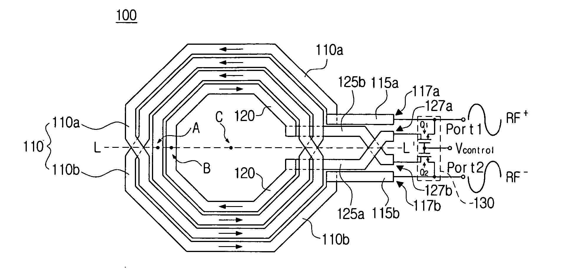
[0035]FIG. 5 is a view showing the configuration of a variable inductor according to an exemplary embodiment of the present invention.

[0036] Referring to FIG. 5, a variable inductor 100 according to an exemplary embodiment of the present invention includes a first lead 110, a second lead 120 and a switch 130.

[0037] The first lea...


PUM


Abstract

A variable inductor is provided, which includes a first lead having both ends to receive a pair of difference signals, a second lead having both ends to receive a pair of the difference signals, and a switch selectively supplying a pair of the difference signals to the second lead by turning on/off according to a control signal. Accordingly, a variable inductor can be implemented that is compact and maximizes the variation rate of inductance.

Description

CROSS-REFERENCE TO RELATED APPLICATIONS [0001] This application claims priority from Korean Patent Application No. 10-2005-0083712, filed Sep. 8, 2005 in the Korean Intellectual Property Office, the entire contents of which are incorporated herein by reference. BACKGROUND OF THE INVENTION [0002] 1. Field of the invention [0003] Apparatuses consistent with the present invention relate to a variable inductor, and more particularly, to an inductor for varying inductance according to an external control signal. [0004] 2. Description of the Related Art [0005] In general, a communications device such as a mobile phone employs semiconductor chip elements to implement a circuit for radio frequency communications. An inductor element is essential to implement such semiconductor chip elements. In particular, a voltage control oscillator (VCO) including an inductor may be used to configure a radio frequency communications circuit for communication at a desired frequency. In these and other app...

Claims


Application Information

Patent Timeline
IPC IPC(8): H01F5/00
CPCH01F17/0013H01F2021/125H01F2017/0046H01F21/12H01F17/0006H01L28/10
Inventor JEON, SANG-YOONJUNG, SUNG-JAELEE, HEUNG-BAELEE, DONG-HYUN
Owner SAMSUNG ELECTRONICS CO LTD
Why Eureka
Try Eureka