Gas purging unit and inkjet head having the same

a gas purging unit and gas inkjet technology, applied in printing and other directions, can solve the problems of reducing the amount of ink that can be used for printing, affecting the printing effect, so as to achieve the effect of effectively and reliably removing gas

Inactive Publication Date: 2007-03-08
SAMSUNG ELECTRONICS CO LTD
View PDF3 Cites 32 Cited by
  • Summary
  • Abstract
  • Description
  • Claims
  • Application Information

AI Technical Summary

Benefits of technology

[0010] The present general inventive concept provides a gas purging unit to effectively and reliably remove gas from a printhead and an ink passage extending from an ink tank to the printhead, and an ink head having the same.

Problems solved by technology

Such superfluously discharged ink either creates unwanted stains on paper or distorts the direction of ink ejection when printing.
During the replacing of the ink tank, if the vacuum needle and the vacuum septum are not thoroughly sealed, air enters the vacuum chamber and can render the pressure of the vacuum chamber insufficient to perform its operations.
Also, if the volume of gas collected in the air pocket is small, excessive vacuum of the vacuum chamber prompts ink to flow through the vacuum needle into the vacuum chamber, rendering the vacuum chamber incapable of performing its operations and reducing the amount of ink that can be used for printing by the amount of ink suctioned into the vacuum chamber.
Furthermore, because each ink tank requires a built-in vacuum chamber and vacuum membrane, production cost increases.

Method used


Image

  • Gas purging unit and inkjet head having the same
  • Gas purging unit and inkjet head having the same
  • Gas purging unit and inkjet head having the same

Examples


Embodiment Construction

[0030] Reference will now be made in detail to the embodiments of the present general inventive concept, examples of which are illustrated in the accompanying drawings, wherein like reference numerals refer to the like elements throughout. The embodiments are described below in order to explain the present general inventive concept by referring to the figures.

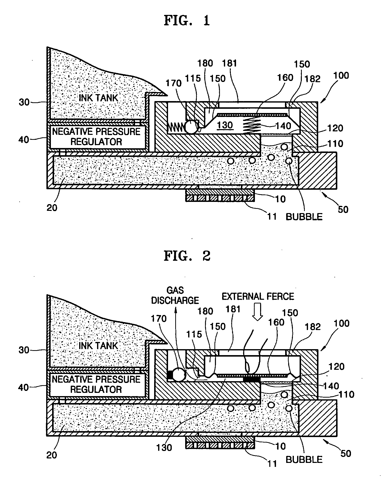
[0031]FIG. 1 is a sectional view of an embodiment of an inkjet head and gas purging unit of the present general inventive concept. Referring to FIG. 1, a cartridge 50 includes an ink passage 20 and a printhead 10. An ink tank 30 to store ink may be coupled to the cartridge 50. Alternately, the ink tank 30 may be connected to the ink passage 20 through an ink tube (not shown), instead of being coupled to the cartridge 50.

[0032] The printhead 10 has a plurality of nozzles 11 to discharge ink. The printhead 10 is provided with a chamber communicating through the plurality of nozzles 11 and having a discharging device (such as a ...


PUM


Abstract

A gas purging unit and an inkjet head with the same. The gas purging unit has an exhaust chamber with a connecting hole to communicate with an ink passage and an exhaust hole that communicates with an outside. A gas permeable membrane is installed at the connecting hole. A negative pressure generator is provided inside the exhaust chamber to operate through an external force and generate a negative pressure with less pressure than a pressure inside the ink passage. A check valve is installed at the exhaust hole to open the exhaust hole when the external force operates the negative pressure generator and to close the exhaust hole by a force of the negative pressure after the external force is removed.

Description

CROSS-REFERENCE TO RELATED APPLICATIONS [0001] This application claims the benefit of Korean Patent Application No. 10-2005-0082626, filed on Sep. 6, 2005, in the Korean Intellectual Property Office, the disclosure of which is incorporated herein in its entirety by reference. BACKGROUND OF THE INVENTION [0002] 1. Field of the Invention [0003] The present general inventive concept relates to a gas purging unit to outwardly purge gas from ink and to an inkjet head having the same. [0004] 2. Description of the Related Art [0005] Gas inherent in ink has a tendency to expand with a temperature fluctuation (from low to high temperatures) or a pressure change (from high to low pressure). The gas is mostly air and small quantities of gases derived from the ingredients in the ink. When there is an absence of a device, such as a gas purging unit, that absorbs the expanded volume of gas and controls the pressure of ink inside ink passages when gas expands, an amount of ink equivalent to the vo...

Claims


Application Information

Patent Timeline
Patent Type & Authority Applications(United States)
IPC IPC(8): B41J2/175
CPCB41J2/19B41J2/17596
Inventor JUNG, MYUNG-SONG
Owner SAMSUNG ELECTRONICS CO LTD
Why Eureka
Try Eureka