Flue gas decarburization system and method utilizing magnetized gas-liquid-solid three phase bed

A three-phase bed and flue gas technology, applied in the field of air pollutant control, can solve the problems of blocking packing, difficult to improve the removal rate, short gas-liquid contact time, etc. The effect of reducing operating costs and reducing energy consumption for regeneration

Inactive Publication Date: 2017-07-14
NANJING NORMAL UNIVERSITY
View PDF3 Cites 6 Cited by
  • Summary
  • Abstract
  • Description
  • Claims
  • Application Information

AI Technical Summary

Problems solved by technology

The mass transfer area of ​​the sieve plate column is small, the structure is complex, and most of them work under pressure
Chinese patent document CN101423214A uses a packed tower for decarburization, the packed tower has a large production capacity and high separation efficiency, but when ammonia water absorbent is used, ammonia water and CO 2 The reaction product of the reaction product will form crystallization and plug the packing
However, when the flue gas flow rate is large, the gas-liquid contact time is short, and the CO 2 It is difficult to improve the removal rate

Method used


Image

  • Flue gas decarburization system and method utilizing magnetized gas-liquid-solid three phase bed
  • Flue gas decarburization system and method utilizing magnetized gas-liquid-solid three phase bed
  • Flue gas decarburization system and method utilizing magnetized gas-liquid-solid three phase bed

Examples


Embodiment 1

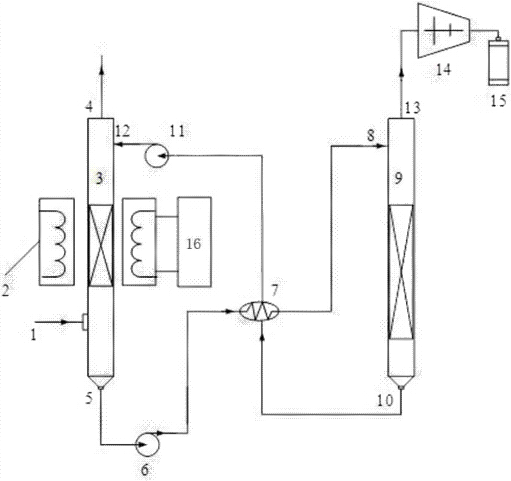
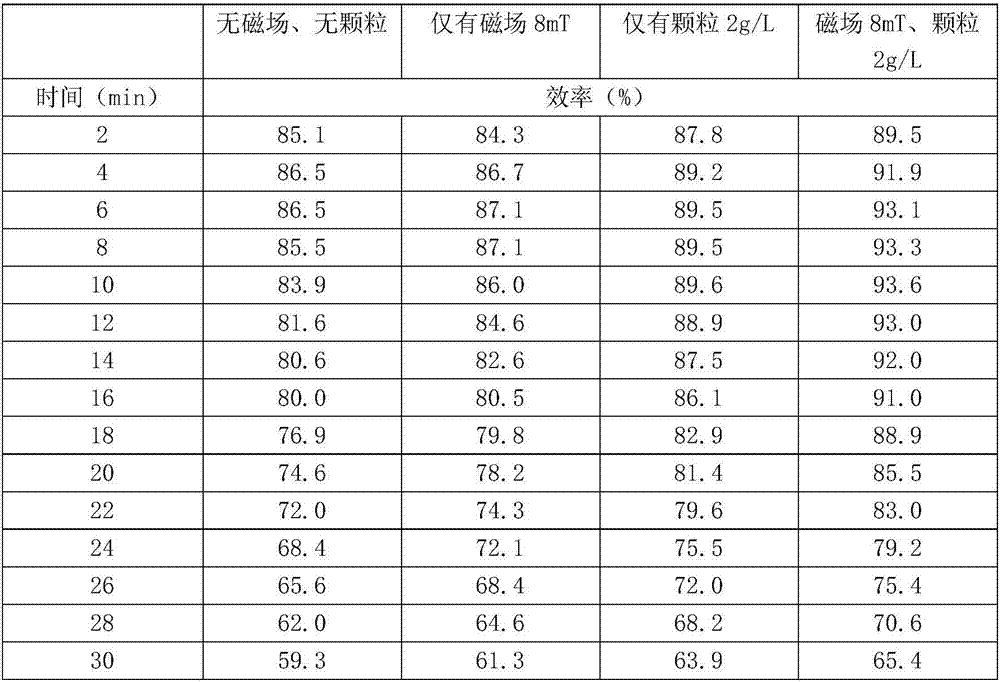
[0040] Use N 2 and CO 2 Gas mixing simulates flue gas, ammonia water absorbent, Fe 3 o 4 Nanoparticles and constant temperature vertical magnetic field, at a reaction temperature of 20°C, a simulated flue gas flow rate of 2.0L / min, a concentration of ammonia water of 5%, CO 2 Under the working condition of 20% concentration, four conditions of no magnetic field and no particles, only magnetic field, only particles, and synergistic effect of particles and magnetic field were selected to investigate the influence of magnetic field and magnetic particles in the absorption tower on the decarburization efficiency. The results are shown in Table 1.

[0041] Table 1: Decarbonization efficiency at different times

[0042]

Embodiment 2

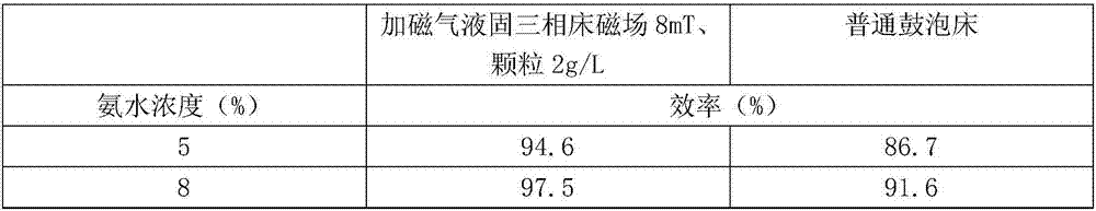
[0044] The implementation process is the same as in Example 1, and the difference in the influence of operating parameters such as ammonia concentration and flue gas flow rate on the decarburization efficiency is investigated by choosing a magnetic gas-liquid-solid three-phase bed and a common bubbling bed (without magnetic field and particles). The results are shown in Table 2 and Table 3.

[0045] Table 2: Decarburization Efficiency of Different Ammonia Concentrations

[0046]

[0047]

[0048] Table 3: Decarbonization efficiency of different flue gas flows

[0049]


PUM


Abstract

The invention discloses a flue gas decarburization system and method utilizing a magnetized gas-liquid-solid three phase bed, and belongs to the technical field of atmospheric pollutant treatment. The system comprises a magnetized three phase bed absorbing tower, a rich and lean solution heat exchanger, a regeneration tower, and a CO2 storage device. The magnetized three phase bed absorbing tower is connected to the rich and lean solution heat exchanger, the regeneration tower and the CO2 storage device in sequence through pipelines. The regeneration tower is provided with a lean solution outlet, is connected to the rich and lean solution heat exchanger through a pipeline, and is connected to the magnetized three phase bed absorbing tower through a pipeline. CO2 is absorbed by an absorbing agent under the co-effect of magnetic field and magnetic particles. A CO2 rich solution flows through the rich and lean solution heat exchanger and releases CO2 in the regeneration tower, and a CO2 lean solution is obtained at the same time. The lean solution flows through the rich and lean solution heat exchanger, goes back to the three phase bed, and keeps on absorbing CO2. The system utilizes a magnetic field and magnetic particles to increase the CO2 absorption efficiency of an absorbing agent; the rich solution and lean solution both carry with few magnetic particles, which can enhance the heat exchange between rich and lean solutions and the regeneration of absorbing solution and the energy consumption of regeneration is reduced therefore.

Description

technical field [0001] The invention belongs to the technical field of air pollutant treatment, and in particular relates to a flue gas decarbonization system and method using a magnetically added gas-liquid-solid three-phase bed. Background technique [0002] Fossil fuels are the main energy source for humans today, but the combustion of fossil fuels produces a large amount of CO 2 emissions, leading to global warming. in CO 2 The implementation of carbon capture and storage (CCS) in intensive emission industries (such as coal-fired power plants) is the most effective way to solve the contradiction between energy demand and climate change. CCS technology is composed of carbon capture, transportation and storage, among which the cost of carbon capture accounts for 70-80% of the total cost, which is the most critical link. Carbon capture technologies include pre-combustion carbon separation technology, oxygen-enriched combustion technology, chemical looping combustion tech...

Claims


Application Information

Patent Timeline
IPC IPC(8): B01D53/62B01D53/96B01D53/78
CPCB01D53/62B01D53/96B01D2251/2062B01D2259/814B01D2259/124B01D2258/0283B01D2257/504Y02A50/20
Inventor 张琦卢平刘巍吴佳艺吴涛
Owner NANJING NORMAL UNIVERSITY
Why Eureka
Try Eureka