Condenser Microphone

a condenser microphone and microphone body technology, applied in the direction of transducer details, electrostatic transducer microphones, electrical transducers, etc., can solve the problems of incidental noise, vibration of the electronic circuit mounted on the circuit board, and general unidirectional sound, so as to reduce the volume of the space, eliminate incidental noise, and excellent frequency response characteristics

Inactive Publication Date: 2014-01-02
AUDIO-TECHNICA
View PDF5 Cites 8 Cited by
  • Summary
  • Abstract
  • Description
  • Claims
  • Application Information

AI Technical Summary

Benefits of technology

[0015]the volume restrictor reduces the volume of the space and prevents sound waves entering the space through the openings from reaching the electronic circuit.
[0016]According to the present invention, the space inside the microphone case communicating with the rear acoustic terminal of the condenser microphone unit and the openings of the microphone case has a volume reduced by the volume restrictor and therefore does not resonate, so that the microphone shows excellent frequency response characteristics. Sound waves with high acoustic pressure entering the microphone case are blocked by the volume restrictor from the electronic circuit. This eliminates incidental noise caused by vibration of the electronic circuit elements.

Problems solved by technology

Such sounds have unidirectionality in general.
When such a condenser microphone is used near instruments, for example, sound waves with high acoustic pressure entering the microphone case cause vibration of the circuit board.
The vibration of the electronic circuit mounted on the circuit board induces incidental noise other than intended sounds to be electro-acoustically converted by the microphone unit.
Such incidental noise results in deterioration in sound quality.
Since the space serves as acoustic capacitance, the acoustic mass of the space and the openings of the microphone case generate resonance, which deteriorates the frequency response of the microphone.
However, the invention according to Japanese Unexamined Patent Application Publication No. 2011-9807 does not intend to include an electronic circuit in such a small space inside the microphone case, and also not intend to prevent the electronic circuit from vibrating in response to sound waves entering the microphone case.

Method used


Image

  • Condenser Microphone
  • Condenser Microphone
  • Condenser Microphone

Examples


embodiment

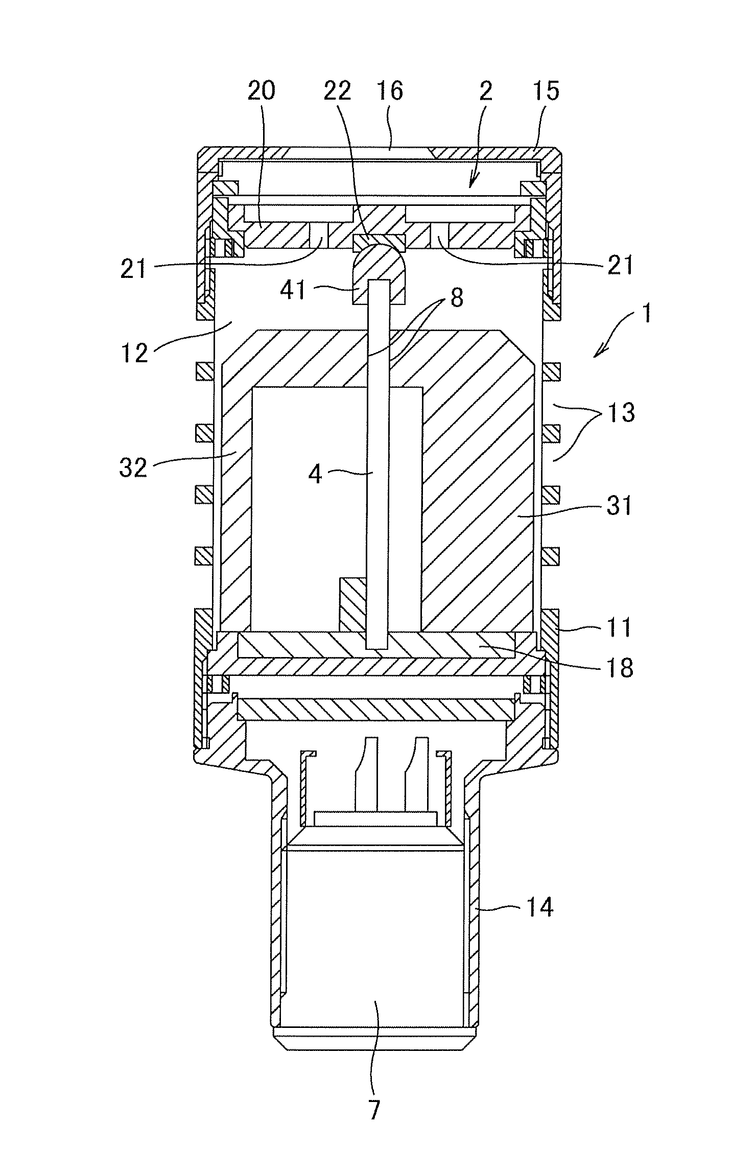
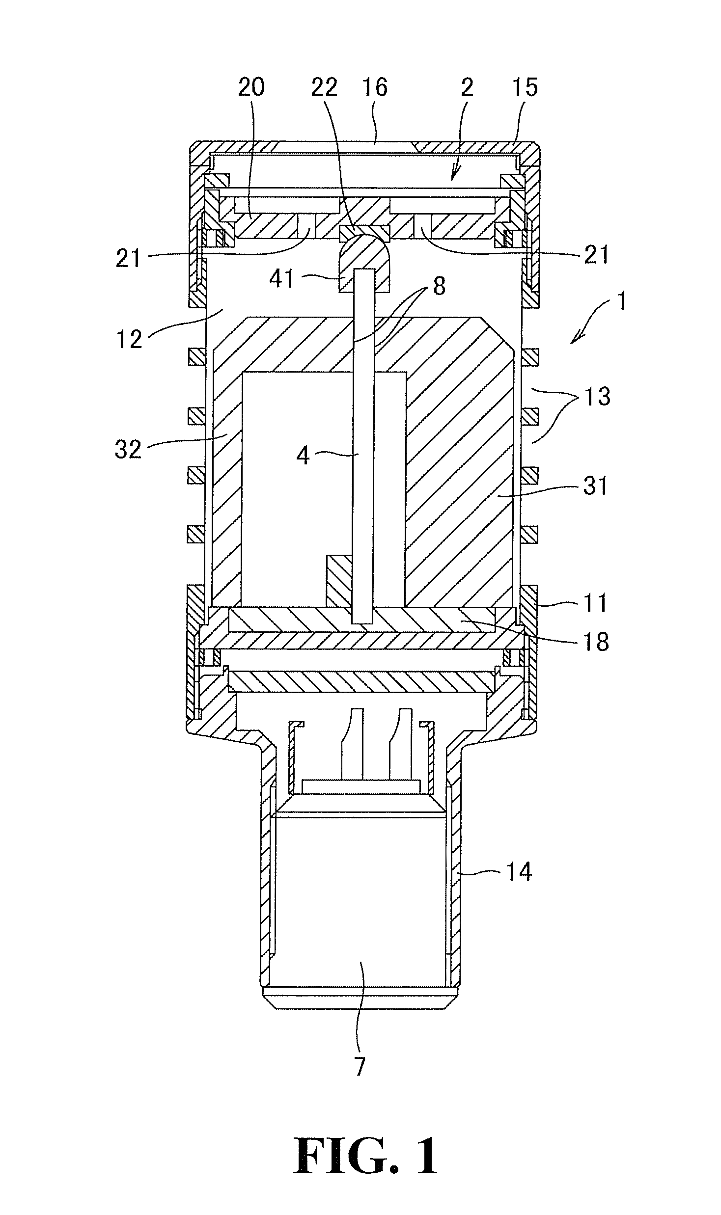
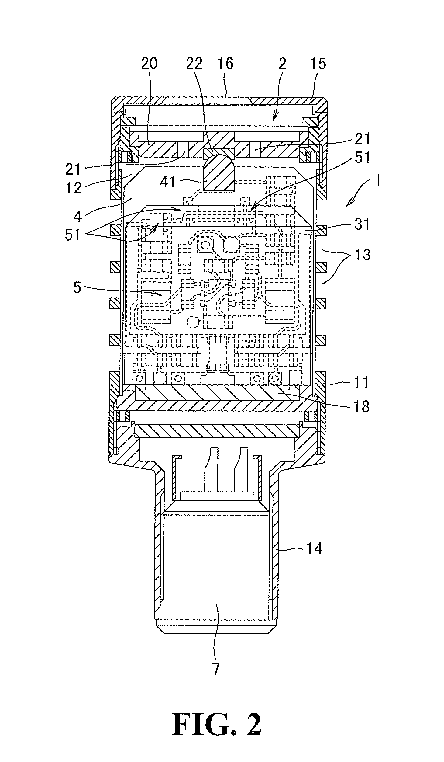
[0020]In FIGS. 1 and 2, a microphone case 1 includes a cylindrical segment 11 that is a main side wall thereof, a head segment 15 that is a cap for the front mouth of the cylindrical segment 11, and a connector segment 14 coupled with the rear mouth of the cylindrical segment 11. The cylindrical segment 11 has an internal space 12, and accommodates a condenser microphone unit 2 at the front therein. The condenser microphone unit 2 has unidirectionality. The cylindrical segment 11 has an appropriate number of openings 13 such that the space 12 inside the cylindrical segment 11 communicates with the openings 13 and is open to the exterior of the microphone through the openings 13.

[0021]As is well known, the condenser microphone unit 2 includes a diaphragm vibrating in response to sound waves and a counter electrode 20 fixed opposite to the diaphragm with a minute interval. The diaphragm and the counter electrode 20 define a capacitor. Vibration of the diaphragm is electro-acoustically...


PUM


Abstract

A condenser microphone includes a volume restrictor disposed in a space inside a microphone case and an electronic circuit disposed in the space and encompassed by the volume restrictor. The volume restrictor reduces the volume of the space and prevents sound waves entering the space through openings on the microphone case from reaching the electronic circuit.

Description

TECHNICAL FIELD[0001]The present invention relates to a condenser microphone that can prevent vibration of an electronic circuit even under high acoustic pressure and provide excellent frequency response and high-quality audio signals without incidental noise.BACKGROUND ART[0002]Microphones have been known that are used under high acoustic pressure near musical instruments to acquire sounds of the instruments. Condenser microphones are commonly employed for use near instruments, which can be more easily downsized than dynamic microphones so as not to obstruct the performer's action or view. Sounds of instruments acquired by the microphone are often subjected to amplification (also referred to as “PA (Public Address)”) at a concert hall, for example. Such sounds have unidirectionality in general. A unidirectional condenser microphone includes a microphone case having openings on its side wall, the openings communicating with a rear acoustic terminal provided at a condenser microphone...

Claims


Application Information

Patent Timeline
Patent Type & Authority Applications(United States)
IPC IPC(8): H04R3/00
CPCH04R3/00H04R19/04H04R27/00
Inventor AKINO, HIROSHI
Owner AUDIO-TECHNICA
Why Eureka
Try Eureka