Oil strainer for automatic transmission

a technology of automatic transmission and oil strainer, which is applied in the direction of gearing details, separation processes, filtration separation, etc., can solve the problems of air accumulated in the air entering the oil chamber, and it takes a relatively long time to produce the desired pressure of the working oil, so as to reduce the volume of the space and effectively suppress the air entrainment

Active Publication Date: 2006-04-06
JATCO LTD +1
View PDF8 Cites 7 Cited by
  • Summary
  • Abstract
  • Description
  • Claims
  • Application Information

AI Technical Summary

Benefits of technology

[0005] The inventors of the present invention have found that there is a relationship between a volume of the air accumulated in a space below a filter within an oil strainer and a hydraulic pressure rise time during which a hydraulic pressure is varied from a minimum value, for instance, 0, at which an operation of the oil pump starts with engine startup, to a desired value. On the basis of this finding, the present invention has been made. That is, it has been found that the above-described problem of the conventional art can be solved by reducing a volume of the space below the filter within the oil strainer with maintaining a performance of the oil strainer. An object of the present invention is to provide an oil strainer capable of effectively suppressing entrainment of air into a working oil in an automatic transmission while maintaining a performance of the oil strainer.

Problems solved by technology

When the engine is started again to drive an oil pump and supply the working oil, the air accumulated enters into the oil pump to interfere with the proper supply of the working oil by the oil pump.
This will cause such a problem that it takes a relatively long time to produce a desired pressure of the working oil.

Method used


Image

  • Oil strainer for automatic transmission
  • Oil strainer for automatic transmission
  • Oil strainer for automatic transmission

Examples


Embodiment Construction

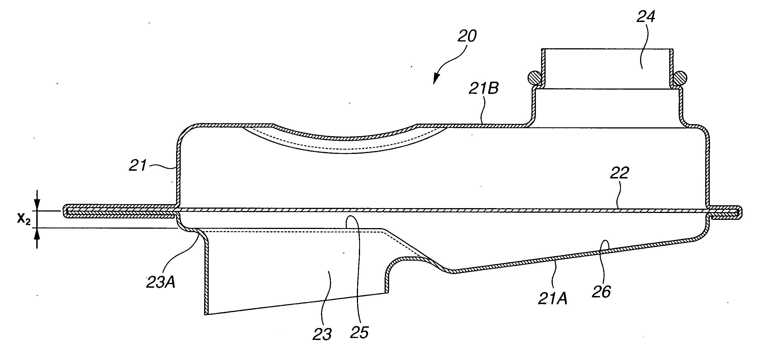
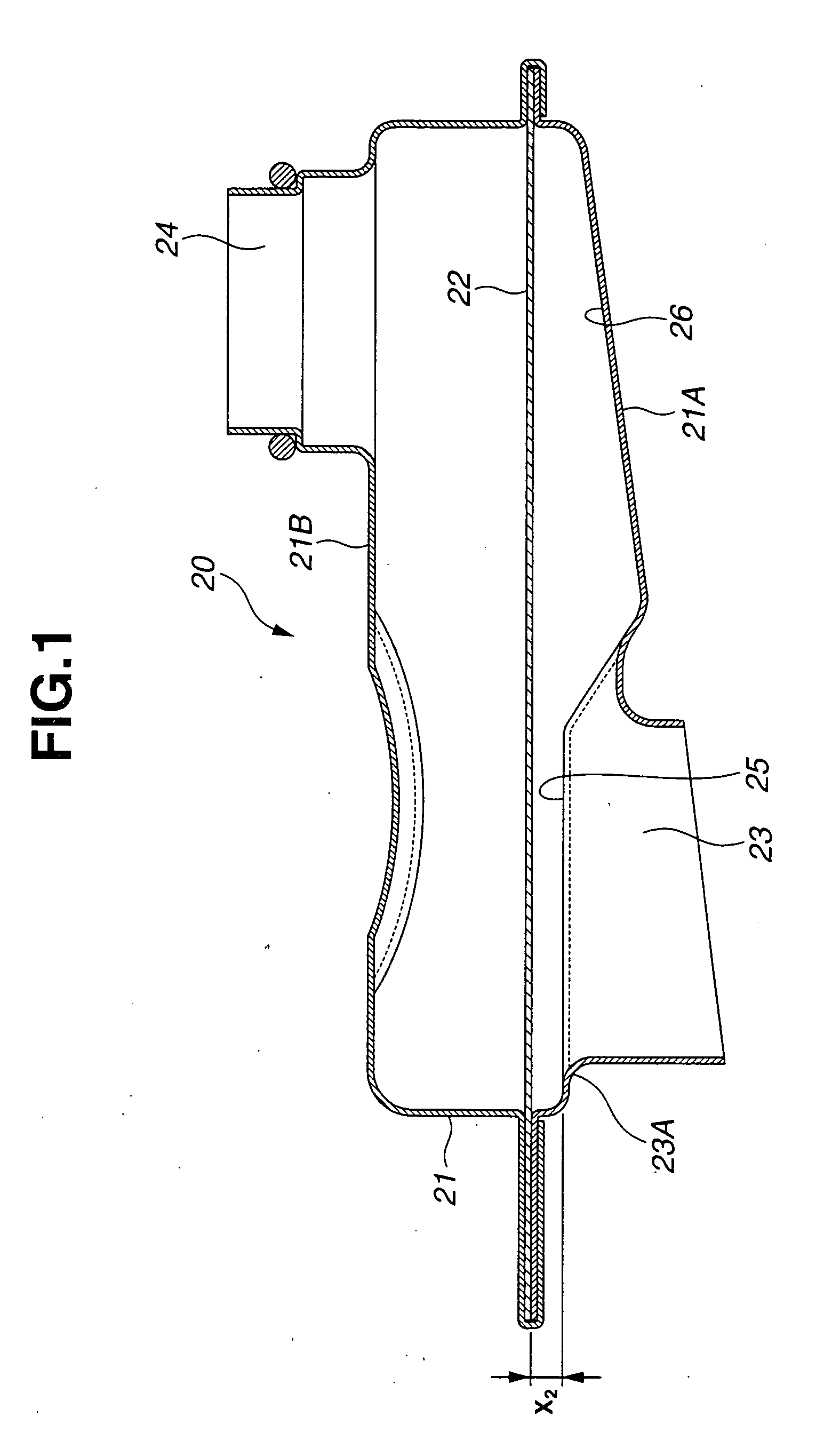
[0022] In the followings, embodiments of the present invention will be described with reference to the accompanying drawings. FIG. 1 is a vertical cross-section of an oil strainer according to a first embodiment of the present invention. As illustrated in FIG. 1, oil strainer 20 includes body 21 and filer 22 substantially horizontally disposed within body 21. Body 21 includes lower wall 21A and upper wall 21B which are disposed on lower and upper sides of oil strainer 20 in a vertical direction, i.e., an up-and-down direction of oil strainer 20, respectively. Filter 22 is in the form of a mesh and arranged to divide an inside space of body 21 into a lower space section and an upper space section. Filter 22 may be placed in a substantially central position within body 21 in the vertical direction of oil strainer 20. Thus, the lower space section is defined between filter 22 and lower wall 21A, and the upper space section is defined between filter 22 and upper wall 21B. Oil strainer 2...


PUM

PropertyMeasurementUnit
temperatureaaaaaaaaaa
areaaaaaaaaaaa
vertical distanceaaaaaaaaaa

Abstract

An oil strainer including a body including lower and walls and an inside space between the lower and upper walls, a filter substantially horizontally disposed within the body so as to divide the inside space into lower and upper space sections, an outlet port provided on the upper wall of the body and communicated with the upper space section, and an inlet port provided on the lower wall of the body and communicated with the lower space section. The lower wall includes a first area in which an inlet port periphery of the inlet port is disposed, and a second area separate from the first area. A vertical distance between the filter and the lower wall in the first area is smaller than a vertical distance between the filter and the lower wall in the second area.

Description

BACKGROUND OF THE INVENTION [0001] The present invention relates to an oil strainer for an automatic transmission, which is provided in a hydraulic system for supplying a working oil to the automatic transmission in order to remove foreign matters, such as dust contained in the oil. [0002] Japanese Patent Application First Publication No. 2004-28145 describes an oil strainer including a body, a filter disposed at a central portion of the body, an inlet port formed at a lower wall of the body, and an outlet port formed at an upper wall of the body. The outlet port is communicated with an oil pump. The oil pump is driven to suck an oil stored within an oil pan into the oil strainer through the inlet port. The oil sucked is filtered through the filter and then discharged from the outlet port and fed to parts of an automatic transmission via hydraulic passages. [0003]FIG. 3 illustrates a conventional oil strainer in vertical cross-section. As shown in FIG. 3, conventional oil strainer 1...

Claims


Application Information

Patent Timeline
Patent Type & Authority Applications(United States)
IPC IPC(8): B01D35/28B01D29/01F16H57/02F16H57/04
CPCF16H57/027F16H57/0404B01D35/00
Inventor NISHIYAMA, HIROYUKIHIRAOKA, YOUJIHIROTSU, SHINGO
Owner JATCO LTD
Why Eureka
Try Eureka