Imaging apparatus with auto-focus function

a technology of auto-focus and imaging apparatus, which is applied in the direction of camera focusing arrangement, printers, instruments, etc., can solve the problems of short time required for auto-focus processing and the inability to display the image of the subject through the auto-focus processing

Inactive Publication Date: 2007-03-08
CASIO COMPUTER CO LTD
View PDF5 Cites 15 Cited by
  • Summary
  • Abstract
  • Description
  • Claims
  • Application Information

AI Technical Summary

Benefits of technology

[0011] According to another aspect of the present invention, there is provided an imaging apparatus including a first image pickup device that converts light from a subject to image data; a second image pickup device that coverts light from a subject to image data; a first drive section that drives the first image pickup device; a second drive section that drives the second image pickup device; a first auto-focus section that changes length of an optical path step by step, that obtains an auto-focus evaluation value based on image data read from the second image pickup device when the length of the optical path is changed, and that controls the length of optical path of light from the subject being incident on the second image pickup device to provide a highest auto-focus evaluation value among the obtained auto-focus evaluation values to perform an auto-focus operation on the subject; and a first control section that controls the first drive section so that the image data is read from the first image pickup device at a predetermined read out cycle suitable for displaying a through image; and that controls the first auto-focus section to perform an auto-focus operation while controlling the second drive section so that the image data is read from the second image pickup device at a shorter read out cycle than the predetermined read out cycle.

Problems solved by technology

If the read out cycle is short, the time required for auto-focus processing becomes short, accordingly.
On the contrary, there is a disadvantage in that the through image of the subject cannot be displayed when auto-focus processing is being performed (see FIG. 2B).

Method used


Image

  • Imaging apparatus with auto-focus function
  • Imaging apparatus with auto-focus function
  • Imaging apparatus with auto-focus function

Examples


first embodiment

[First Embodiment]

A. Configuration of Digital Camera

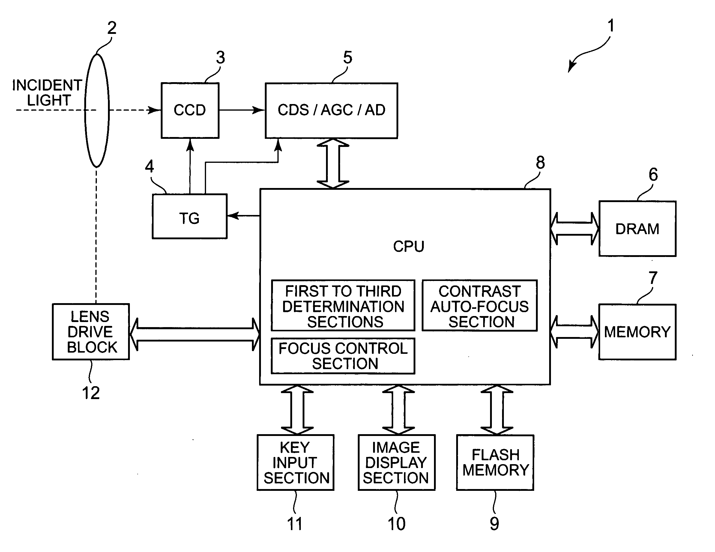
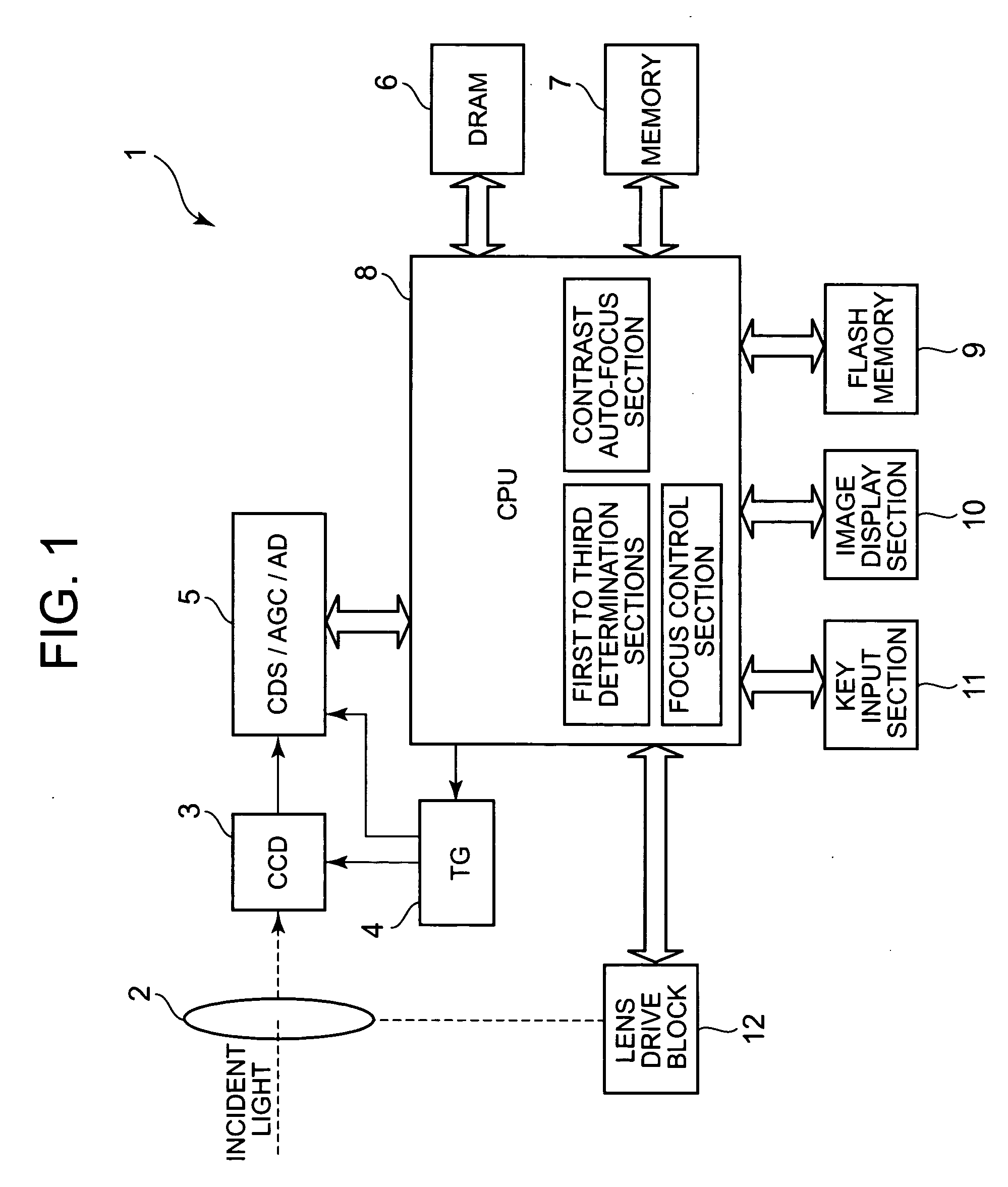
[0026]FIG. 1 is a block diagram illustrating a schematic configuration of a digital camera 1 that implements the imaging apparatus of the present invention.

[0027] The digital camera 1 includes a shooting lens 2, a CCD 3, a TG (Timing Generator) 4, a unit circuit 5, a DRAM 6, a memory 7, a CPU 8, a flash memory 8, an image display section 10, a key input section 11, and a lens drive block 12.

[0028] The shooting lens 2 includes a focus lens and a zoom lens (both not shown in the figure), and a lens drive block 12 is connected thereto. The lens drive block 12 includes a focus motor and a zoom motor that drive the focus lens and the zoom lens (both not shown), respectively, in a direction of an optical axis, and a focus motor driver and a zoom motor driver that drives the focus motor and zoom motor, respectively, in the direction of the optical axis according to a control signal from the CPU 8.

[0029] The CCD 3 converts light from ...

second embodiment

[Second Embodiment]

[0086] Next, the second embodiment will be explained.

F. Configuration of Digital Camera

[0087]FIG. 6 is a block diagram illustrating a schematic configuration of a digital camera 21 that implements the imaging apparatus of the present invention.

[0088] The digital camera 21 of the second embodiment includes a shooting lens 2, a CCD 3, a TG (Timing Generator) 4, a unit circuit 5, a DRAM 6, a memory 7, a CPU 8, a flash memory 8, an image display section 10, a key input section 11, a drive circuit 22, a drive circuit 23, an optical path division section 24, a CCD 25, a TG 26, and a unit circuit 27.

[0089] Regarding the same sections as those of the first embodiment, the same reference numerals as those of FIG. 1 are given to the corresponding sections of FIG. 6.

[0090] The drive circuit 22 includes a motor and a motor driver to drive the CCD 3 in a direction of the optical axis. The drive circuit 22 drives the CCD 3 in the direction of the optical axis according to...


PUM


Abstract

An imaging apparatus includes an image pickup device that converts light from a subject to image data a drive section that drives the image pickup device, an auto-focus section that performs an auto-focus operation, and a focus control section that controls the auto-focus section to perform an auto-focus operation while controlling the drive section so that the image data is read from the image pickup device at a predetermined read out cycle suitable for displaying a through image, when the first determination section determines that the shutter button is pressed halfway, and that controls the auto-focus section to perform an auto-focus operation while controlling the drive section so that the image data is read from the image pickup device at a shorter read out cycle than the redetermined read out cycle, when the second determination section determines that the shutter button is fully pressed at once.

Description

BACKGROUND OF THE INVENTION [0001] 1. Field of the Invention [0002] The present invention relates to an imaging apparatus having an auto-focus function usable in a digital camera and relates to an auto-focus control method. [0003] 2. Description of the Related Art [0004] An auto-focus processing by a contrast detection method is one of typical methods for bringing a subject into focus. The auto-focus processing by the contrast detection method is as follows; (1) a focus lens is driven from a lens end to a lens end within a drivable range of a lens; (2) a contrast component is detected from an imaging signal, which is a CCD output at this time, and (3) its waveform is interpreted, thereby moving a lens to a lens position having a highest frequency component in order to achieve focus. [0005] Accordingly, the speed of auto-focus processing by the contrast detection method depends on a cycle speed in which the image data is read out from the CCD (read out cycle). If the read out cycle i...

Claims


Application Information

Patent Timeline
Patent Type & Authority Applications(United States)
IPC IPC(8): G03B13/00
CPCH04N5/23212G03B13/36H04N23/673H04N23/63G03B17/02G03B3/10
Inventor ONOZAWA, MASARU
Owner CASIO COMPUTER CO LTD
Why Eureka
Try Eureka