Diaphragm for use in speakers and speaker provided with this diaphragm
a diaphragm and speaker technology, applied in the direction of transducer details, electrical transducers, electrical apparatus, etc., can solve the problems of divisional resonance, abnormal resonance, and inability to obtain desired frequency characteristics, and achieve excellent tone quality
- Summary
- Abstract
- Description
- Claims
- Application Information
AI Technical Summary
Benefits of technology
Problems solved by technology
Method used
Image

Examples
embodiment 1
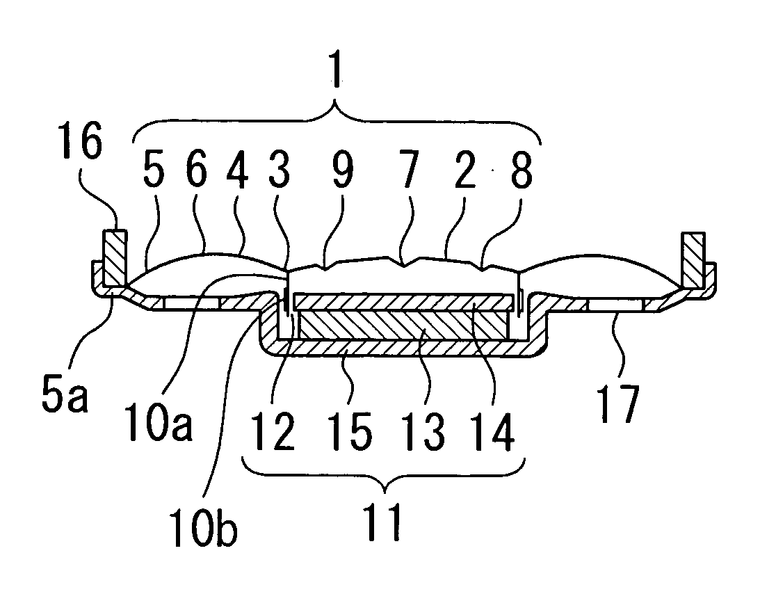
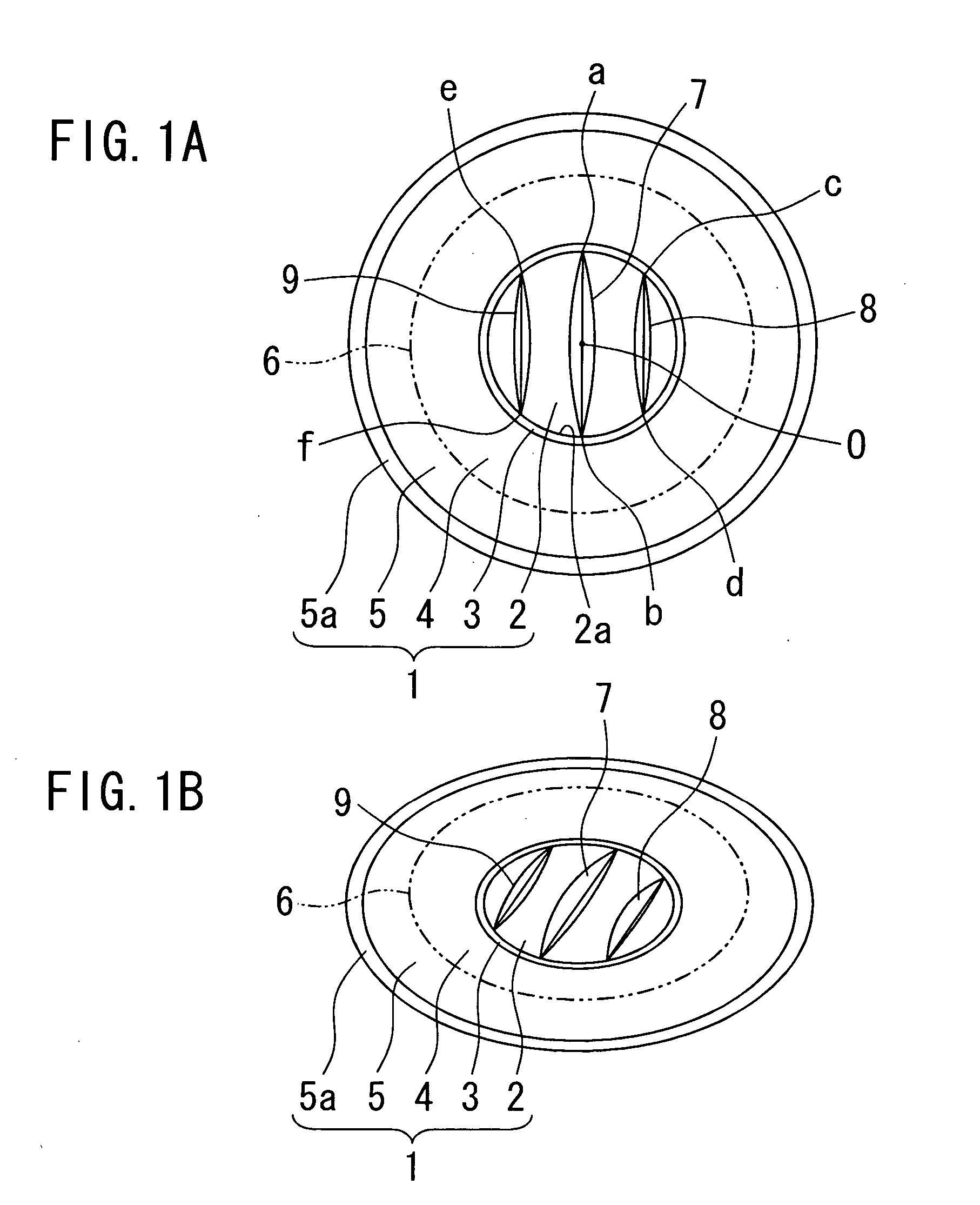
[0036] In FIGS. 1 and 2, a diaphragm 1 for use in speakers in the first embodiment according to the present invention is made as a whole of a circular resin molding, which comprises a center dome 2 forming in the center a dome shape of a large radius of curvature, an annular diaphragm part 4 formed integrally and concentrically with the center dome 2 through an annular voice-coil joining part 3 which is constituted by an outer peripheral edge of the center dome 2, an annular edge 5 constituted by an outer peripheral part of the diaphragm part 4, and a frame joining part 5a provided at outer peripheral end of the edge 5. The diaphragm part 4 swells in the same direction as the center dome 2 and forms an annular ridge 6 shown by a double-dot chain line between the part 4 and the outer peripheral edge 5. The voice-coil joining part 3 is formed, therefore, by means of a valley part between the center dome 2 and the diaphragm part 4 both swelling, or by means of a narrow flat region prov...
embodiment 2
[0051]FIG. 4 shows a second embodiment according to the present invention, in which the rib comprises also the first to third ribs 7A-9A, whereas the central first rib 7A is positioned as deviated from the center O of the center dome 2, and consequently the first rib 7A is disposed to be unequally spaced from each of the second and third ribs 8A and 9A.
[0052] In FIG. 4, the space of the first rib 7A from the second rib 8A on the right-hand side is shown to be smaller, but in contrast the space from the third rib 9A may of course be made smaller.
[0053] In either event, the first to third ribs 7A-9A are disposed to so extend as to reach at both ends the outer periphery 2a of the center dome 2 and to be mutually in parallel.
embodiment 3
[0054]FIG. 5 shows a third embodiment of the present invention, in which a pair of ribs 7B and 8B linearly extending between respectively two points 7b and 7b′ as well as 8b and 8b′ on the outer periphery 2a of the center dome 2, to be in non-parallel, mutually diagonally and non-axial symmetry relationship. Therefore, a space l1 between one end points 7b and 8b of the ribs 7B and 8B and a space l2 between the other end points 7b′ and 8b′ of the ribs 7B and 8B are in the relationship l12.
[0055] In other words, the pair of ribs 7B and 8B are disposed symmetrical, when the diaphragm 1 is viewed from front side, forming both left and right sides of an isosceles trapezoid or triangle.
PUM
 Abstract
Description
Claims
Application Information
 - R&D
- Intellectual Property
- Life Sciences
- Materials
- Tech Scout
- Unparalleled Data Quality
- Higher Quality Content
- 60% Fewer Hallucinations
Browse by: Latest US Patents, China's latest patents, Technical Efficacy Thesaurus, Application Domain, Technology Topic, Popular Technical Reports.
© 2025 PatSnap. All rights reserved.Legal|Privacy policy|Modern Slavery Act Transparency Statement|Sitemap|About US| Contact US: help@patsnap.com