
Hybrid power line wireless communication system

a wireless communication and hybrid technology, applied in powerline communications applications, transmission path division, transmission monitoring, etc., can solve the problems of inability or inability to install fiber optic cables to connect backhaul points to the conventional telecommunications network, inability to allow additional fiber optic cables to be installed, and inability to achieve the effect of reducing latency and increasing system capacity

Inactive Publication Date: 2007-03-08
CURRENT TECH
View PDF65 Cites 285 Cited by
  • Summary
  • Abstract
  • Description
  • Claims
  • Application Information

AI Technical Summary

Benefits of technology

"The present invention is a hybrid power line wireless communication system and method that increases system capacity and reduces latency among nearby end users accessing the network. The system uses both a wireless link and a wired link, which may be a power line link, fiber optic link, coaxial cable link, and / or twisted pair link. The quality of the wireless link is assessed, and if the quality is below a predetermined level, a second wireless link is established using a licensed frequency band. The first link may be terminated after the second link is established. The system can carry communications between an access point of an external network and the power line communication node or between a user device and the communication node in either direction."

Problems solved by technology

However, in some instances it may not be feasible or possible to install fiber optic cable to connect the backhaul point to the conventional telecommunications network.
For example, installing additional fiber optic cable can be cost prohibitive.
In another example, existing infrastructure such as intersections and other obstacles may not allow additional fiber optic cable to be installed.
However, unlicensed wireless links are often not reliable and licensed wireless links are often very expensive
In the conventional PLCS, the router can become a bottleneck as many end user devices vie for access to the router for sending and receiving communications over the PLCS.

Method used


Image

  • Hybrid power line wireless communication system
  • Hybrid power line wireless communication system
  • Hybrid power line wireless communication system

Examples


Embodiment Construction

[0023] In the following description, for purposes of explanation and not limitation, specific details are set forth, such as particular networks, communication systems, computers, PLCS, terminals, devices, components, techniques, data and network protocols, software products and systems, operating systems, development interfaces, hardware, etc. in order to provide a thorough understanding of the present invention.

[0024] However, it will be apparent to one skilled in the art that the present invention may be practiced in other embodiments that depart from these specific details. Detailed descriptions of well-known networks, communication systems, computers, PLCS, terminals, devices, components, techniques, data and network protocols, software products and systems, operating systems, development interfaces, and hardware are omitted so as not to obscure the description of the present invention.

System Architecture and General Design Concepts

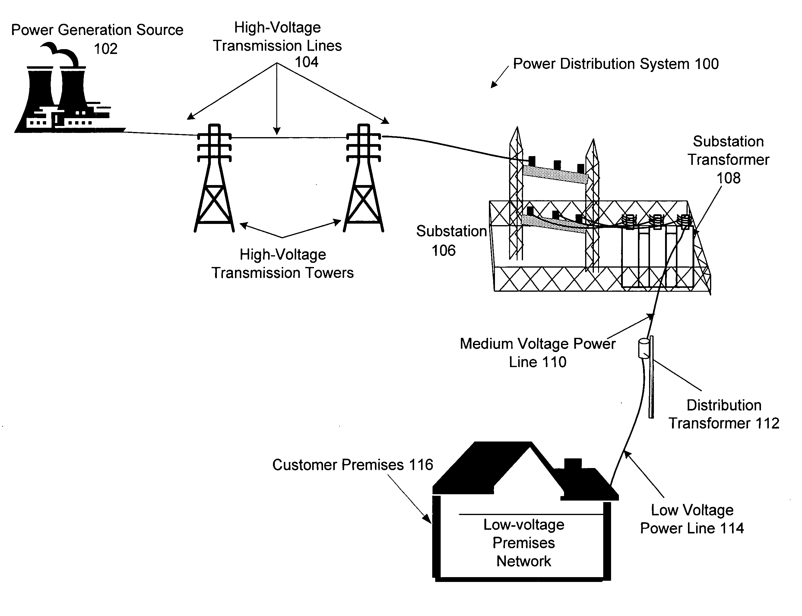
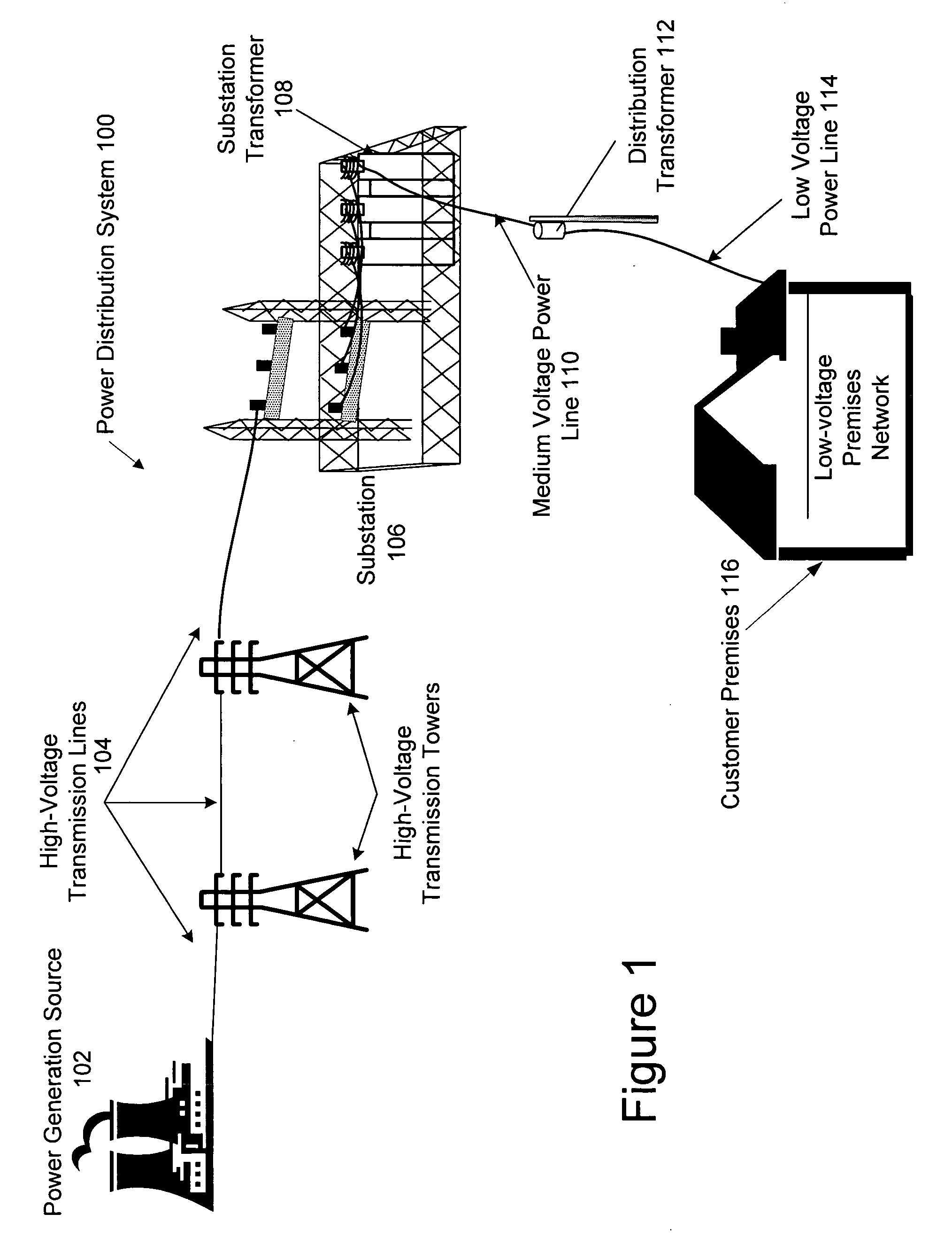
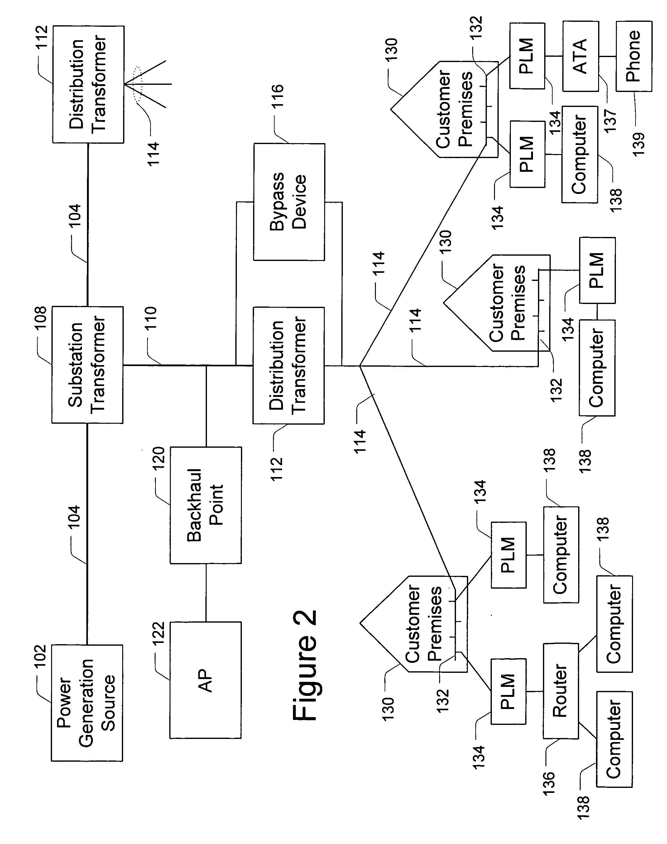
[0025]FIG. 1 illustrates an example power ...


PUM


Abstract

In a hybrid communication system a wireless communication link is maintained between a power line communication medium and a non-power line communication medium. Wireless communication is established within an unlicensed frequency band and monitored for quality. If the quality falls below a threshold, a wireless communication link is established within a licensed frequency band. The wireless link may be maintained between a power line communication system (PLCS) backhaul point and an internet protocol (IP) network access point, and / or between a PLCS endpoint communication interface and a premises communication device.

Description

FIELD OF THE INVENTION [0001] The present invention generally relates to methods and systems of power line communication, and more particularly to interfacing power line communications and wireless communications. BACKGROUND OF THE INVENTION [0002] A power line communication system (PLCS) uses the infrastructure of existing power distributions systems to form a communication network. Well-established power distribution systems exist throughout most of the United States, and other countries providing power to customers via power lines. With some modification, the infrastructure of the existing power distribution system can be used to provide data communication, in addition to conventional power delivery. In other words, existing power lines that already have been run to many homes and offices can be used to carry data signals to and from those homes and offices. These data signals are communicated on and off the power lines at various points in the power line communication system, su...

Claims


Application Information

Patent Timeline
Patent Type & Authority Applications(United States)
IPC IPC(8): H04B17/00
CPCH04B3/542H04B2203/5445H04L1/0001H04B17/382H04L27/2601H04B17/309H04L5/0007
Inventor BERKMAN, WILLIAM H.
Owner CURRENT TECH
Learn More