Heat-effect reduceable finishing unit and image forming system using the same

a technology of heat-effect reduction and finishing unit, which is applied in the direction of manufacturing tools, saw chains, instruments, etc., can solve the problems of blade overloaded, degraded perforation quality, temperature variation between the plurality of parts in the perforator,

Inactive Publication Date: 2007-03-15
RICOH KK
View PDF28 Cites 15 Cited by
  • Summary
  • Abstract
  • Description
  • Claims
  • Application Information

AI Technical Summary

Benefits of technology

[0021] The present disclosure relates to a perforator configured to perforate a sheet including a first frame and a blade. The first frame includes a first main face having a first hole, and is provided under a transport path of the sheet. The blade is moved into the first hole to perforate the sheet transported in the transport path. A bending strength of the first main face in a vertical direction with respect to the transport path of sheet is smaller than a bending strength of the first main face in a parallel direction with respect to the transport path of sheet.
[0022] The present disclosure also relates to another perforator configured to perforate a sheet including a first frame, a second frame, and a blade. The first frame includes a first main face having a first hole, and is provided under a transport path of the sheet. The second frame includes a second main face having a second hole aligned with the first hole in the first main face of the first frame, the second frame being provided over the transport path of the sheet. The blade is moved into the second hole and first hole to perforate the sheet transported in the transport path. A bending strength of the second main face in a vertical direction with respect to the transport path of sheet is smaller than a bending strength of the second main face in a parallel direction with respect to the transport path of sheet.

Problems solved by technology

Such heat may affect a plurality of parts in the perforator, and may cause a temperature variation between the plurality of parts in the perforator.
If such deviation is significant such deflection may hinder the pass-through of the blade in the die hole, and may degrade the perforation quality.
Furthermore, if the blade can not pass through the die hole smoothly, the blade may become overloaded, by which the image forming system may stop the movement of blade, and then an operation of the image forming system may be stopped.

Method used


Image

  • Heat-effect reduceable finishing unit and image forming system using the same
  • Heat-effect reduceable finishing unit and image forming system using the same
  • Heat-effect reduceable finishing unit and image forming system using the same

Examples


Embodiment Construction

[0034] In describing example embodiments shown in the drawings, specific terminology is employed for the sake of clarity. However, the disclosure of the present invention is not intended to be limited to the specific terminology so selected and it is to be understood that each specific element includes all technical equivalents that operate in a similar manner.

[0035] Referring now to the drawings, wherein like reference numerals designate identical or corresponding parts throughout the several views, an image forming system according to an example embodiment is described with particular reference to FIGS. 1 to 6.

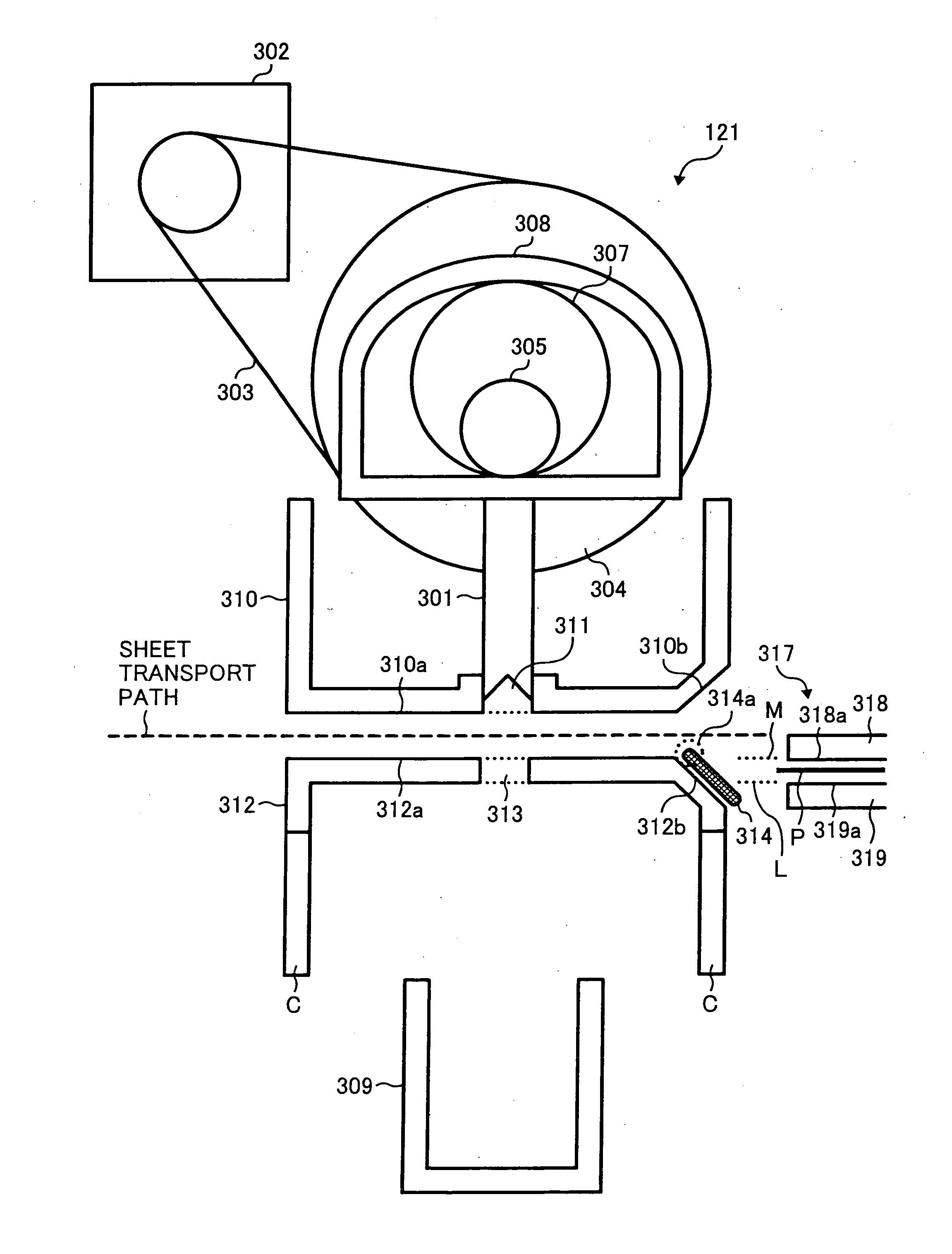
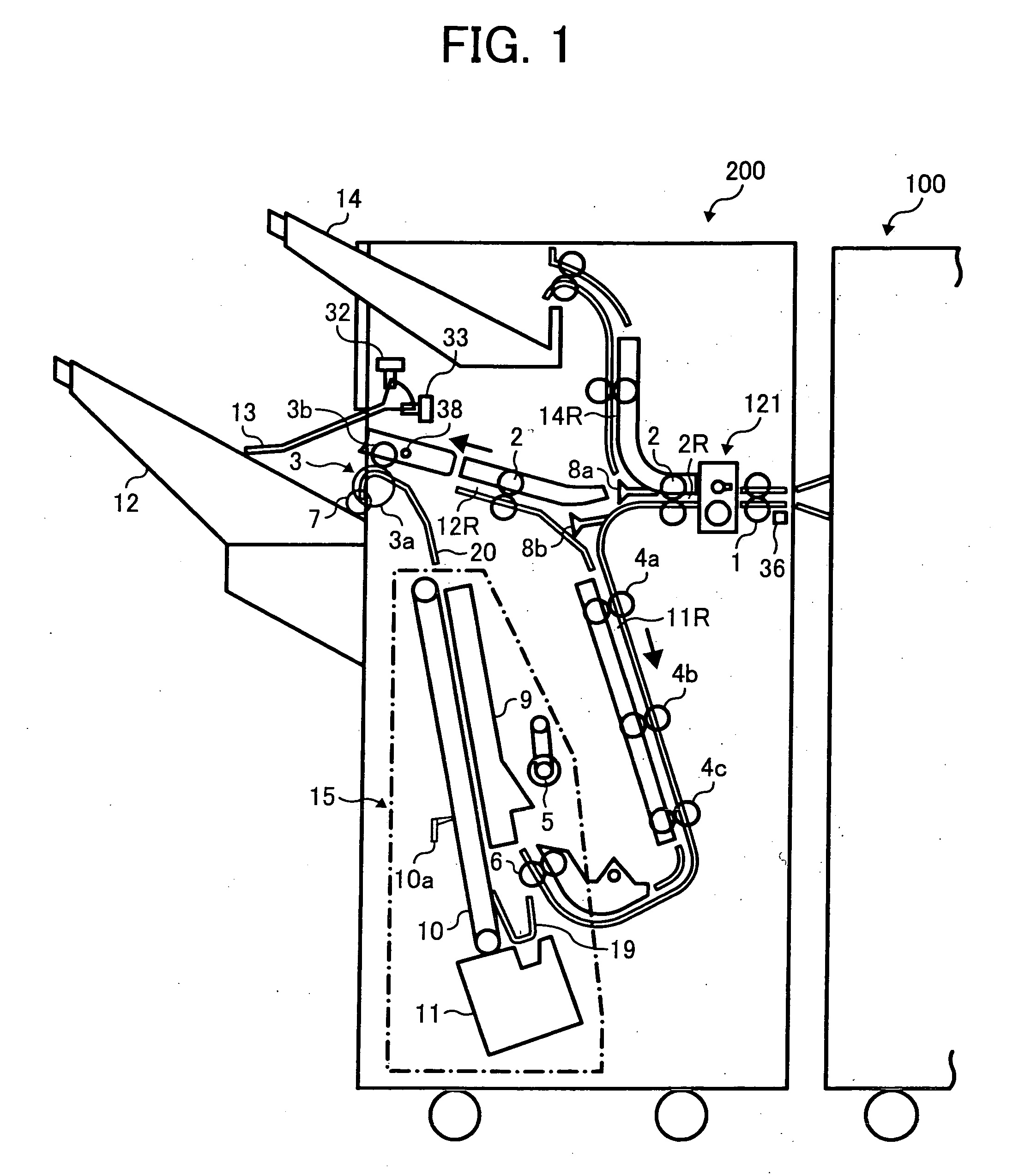
[0036]FIG. 1 is a schematic configuration of an image forming system including an image forming apparatus 100 and a finishing unit 200.

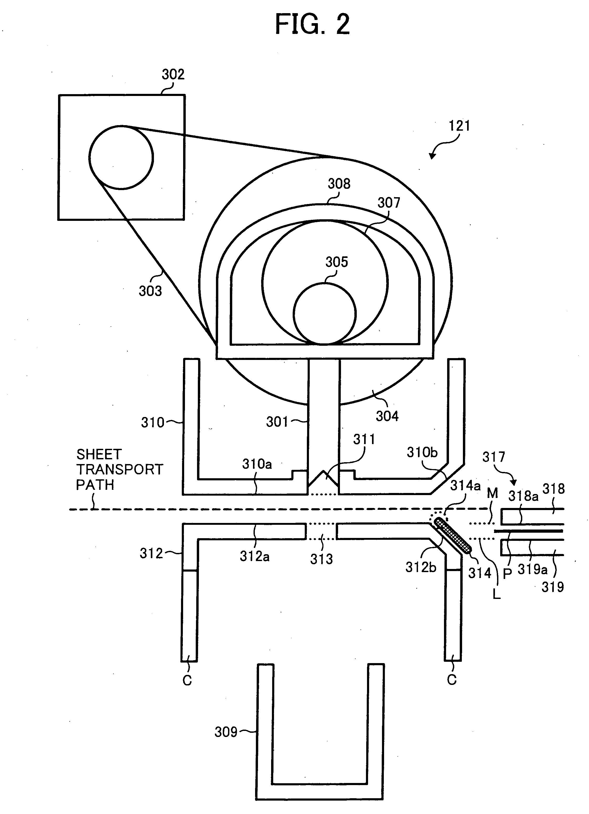
[0037] The image forming apparatus 100 includes a copier, for example. The finishing unit 200, attached next to the image forming apparatus 100, includes a perforator, for example.

[0038] The image forming apparatus 100 includes an image f...


PUM

PropertyMeasurementUnit
bending strengthaaaaaaaaaa
heat conductivityaaaaaaaaaa
temperatureaaaaaaaaaa

Abstract

A perforator configured to perforate a sheet includes a first frame and a blade. The first frame includes a first main face having a first hole, and is provided under a transport path of the sheet. The blade is moved into the first hole to perforate the sheet transported in the transport path. A bending strength of the first main face in a vertical direction with respect to the transport path of the sheet is smaller than a bending strength of the first main face in a parallel direction with respect to the transport path of the sheet.

Description

CROSS-REFERENCE TO RELATED APPLICATIONS [0001] This application claims priority from Japanese Patent Application Nos. 2005-263896, filed on Sep. 12, 2005, and 2006-163562, filed on Jun. 13, 2006, the entire contents of which are incorporated herein by reference. FIELD OF THE INVENTION [0002] The present disclosure generally relates to an image forming system having an image forming unit and a finishing unit, and more particularly to a finishing unit, which processes a sheet transported from an image forming unit. DISCUSSION OF THE BACKGROUND [0003] An image forming apparatus such as printer, copier, facsimile, and MFP (multi-functional peripherals) may be attached with a finishing unit, to which a sheet having an image thereon is ejected from the image forming apparatus. [0004] The finishing unit may include a perforator to perforate a hole on the sheet ejected from the image forming apparatus. [0005] The perforator includes a reciprocal type unit having a die frame, a guide frame, ...

Claims


Application Information

Patent Timeline
Patent Type & Authority Applications(United States)
IPC IPC(8): B26D1/00
CPCB26F1/02G03G2215/00818G03G15/6582B26F1/14Y10T83/293Y10T83/745Y10T83/929Y10T83/9428
Inventor YAMADA, KENJISAITOH, HIROMOTOKIKKAWA, NAOHIROILDA, JUNICHITOKITA, JUNICHIMATSUSHITA, SHINGO
Owner RICOH KK
Why Eureka
Try Eureka