Vehicle-body structure of vehicle

a vehicle and body technology, applied in the direction of vehicle components, vehicular safety arrangments, bumpers, etc., can solve the problems of difficult to ensure the bending strength against impact load, and achieve the light weight of bumper reinforcement, so as to improve the load transmission and lighten the weight of the bumper reinforcement

Inactive Publication Date: 2015-03-24
MAZDA MOTOR CORP
View PDF33 Cites 6 Cited by
  • Summary
  • Abstract
  • Description
  • Claims
  • Application Information

AI Technical Summary

Benefits of technology

[0005]An object of the present invention is to provide a vehicle-body structure of a vehicle which can properly ensure the bending strength and also attain the light weight of the bumper reinforcement, improving the load transmission from the bumper reinforcement to crash cans.
[0007]According to the present invention, since the distance, in the vehicle longitudinal direction, of the step potions of the first panel member from the second panel member is configured such that the distance at the central portion, in the vehicle width direction, of the bumper reinforcement is the maximum and the distance decreases gradually toward the outward direction of the vehicle, the bending strength of the step portions at the central portion, in the vehicle width direction, of the bumper reinforcement where a bending load occurring in a vehicle light collision is the maximum can be made the maximum, whereas the structure of the step portions at both-side portions of the bumper reinforcement where the above-described bending load is smaller can be made properly light (not heavy). Accordingly, the bending strength can be ensured and also the light weight of the bumper reinforcement can be attained. Additionally, the load transmission from the bumper reinforcement to crash cans can be improved.
[0008]According to an embodiment of the present invention, a length (H), in the vehicle longitudinal direction, of the cross section of the bumper reinforcement and the distance (h) of the step potions of the first panel member from the second panel member at the central portion of the bumper reinforcement are configured such that a ratio (h / H) of the distance (h) to the length (H) is 0.2˜0.5. Thereby, the bending strength can be further increased. Herein, in a case in which the value of the ratio (h / H) is smaller than 0.2, the weight becomes light but the bending strength decreases. Meanwhile, in a case in which the value of the ratio (h / H) is greater than 0.5, the weight becomes heavy and also the bending strength decreases. Therefore, by setting the value of the ratio (h / H) in the range of 0.2˜0.5, the bending strength can be further increased, attaining the light weight of the bumper reinforcement.
[0009]According to another embodiment of the present invention, the upper face portion of the first panel member includes a first upper face portion which is located further away from the vertical wall portion and a second upper face portion which is located closer to the vertical wall portion, the lower face portion of the first panel member includes a first lower face portion which is located further away from the vertical wall portion and a second lower face portion which is located closer to the vertical wall portion, and a second angle of the second upper and lower face portions relative to a horizontal direction is configured to be greater than a first angle of the first upper and lower face portions relative to the horizontal direction. Herein, the above-described first or second angle of the first or second upper face portion relative to the horizontal direction means an angle of depression, and the above-described first or second angle of the first or second lower face portion means an angle of ascent. According to the above-described embodiment, since the first angle of the first upper and lower face portions relative to the horizontal direction is relatively small, buckling of the second panel member (closing plate) formed substantially in the flat-plate shape can be prevented properly. Further, since the second angle of the first upper and lower face portions relative to the horizontal direction is relatively great (large), in a case in which the second panel member having the U-shaped cross section is formed through pressing by means of a metal mold, an angle of a corner of the metal mold which is located at the back of the metal mold can be designed so as to be greater (larger), so that the friction against the metal mold can be reduced properly. Consequently, the metal mold can be properly restrained from being worn away. Herein, it is preferable that the first angle of the first upper and lower face portions relative to the horizontal direction be 0˜15° and the second angle of the first upper and lower face portions relative to the horizontal direction be 5° or greater (larger).
[0010]According to another embodiment of the present invention, flange extension portions which extend toward the vehicle compartment are formed at respective end portions of the flange portions. Thereby, substantially a U-shaped portion is formed at a position in a range from the above-described step portions to the flange extension portions, so that the bending strength against the collision load can be further improved.
[0011]According to another embodiment of the present invention, the vehicle-body structure of a vehicle further comprises a pair of front side frames extending in the vehicle longitudinal direction and provided at both sides of the vehicle, and a pair of crash cans provided between front end portions of the front side frames and both-side end portions of the bumper reinforcement, wherein no step portion is formed at the both-side end portions of the bumper reinforcement where the crash cans are provided. Thereby, some sufficient space for welding can be ensured there.

Problems solved by technology

In the conventional structure disclosed in the patent document, however, since the cross section shown in FIG. 10 has the same (identical) shape over its whole width in the vehicle width direction, it may be difficult that the bending strength against the impact load can be ensured and also the light weight of the bumper reinforcement can be attained.

Method used


Image

  • Vehicle-body structure of vehicle
  • Vehicle-body structure of vehicle
  • Vehicle-body structure of vehicle

Examples


Embodiment Construction

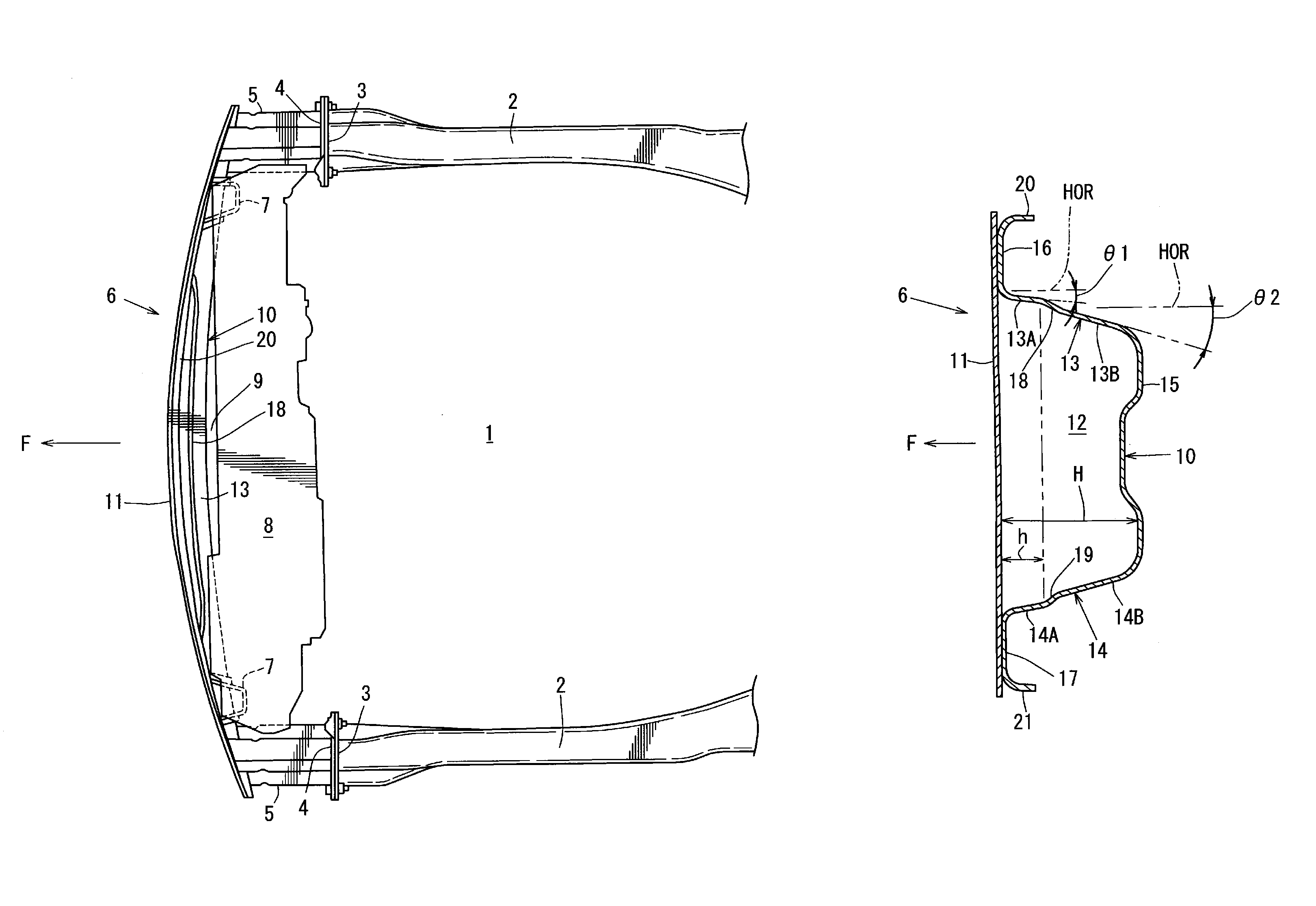
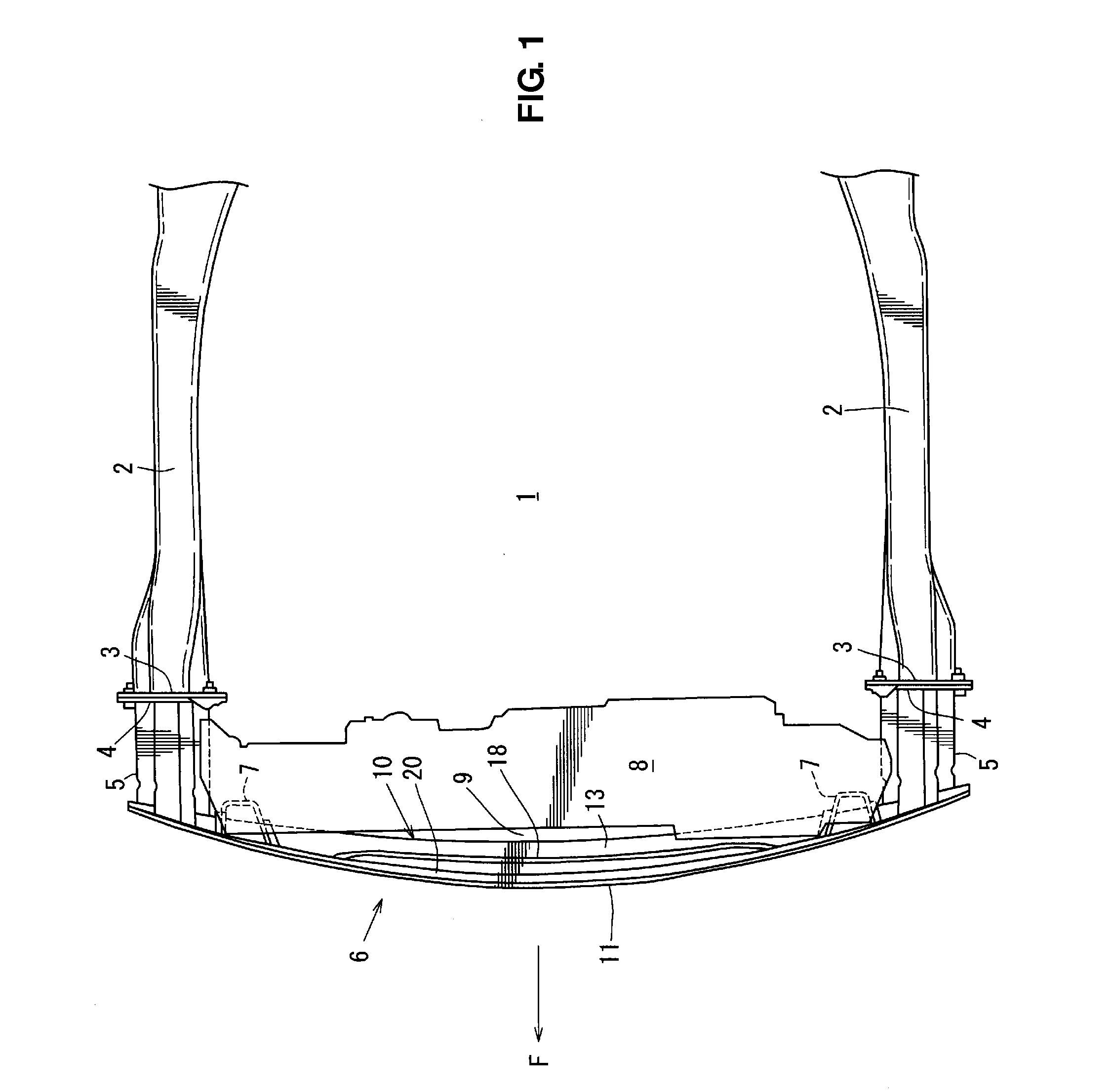
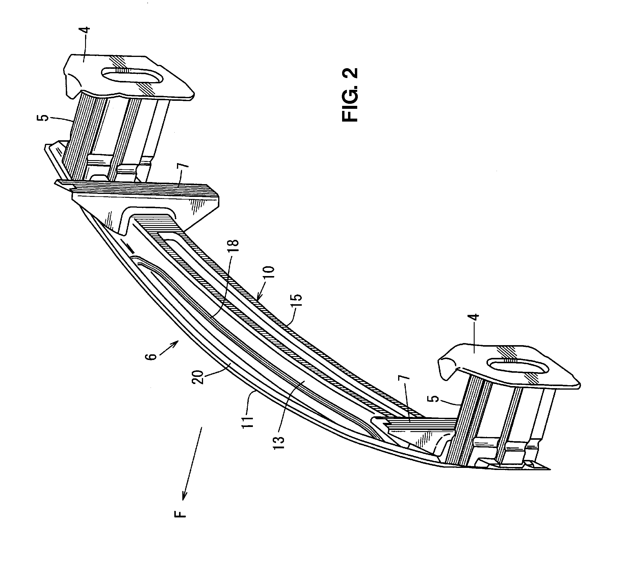
[0023]Hereinafter, a preferred embodiment of the present invention will be described specifically referring to the accompanying drawings. The drawings show a vehicle-body structure of a vehicle, and the vehicle-body structure according to the present invention which is applied to a vehicle front side will be described in the following embodiment. FIG. 1 is a plan view of a vehicle-body structure of a front portion of the vehicle, FIG. 2 is a perspective view of a state in which a cooling unit is removed from FIG. 1, and FIG. 3 is a plan view of FIG. 2. In the figures, an arrow F shows a forward direction of the vehicle. In FIGS. 2˜3, front side frames 2, 2 which extend in a vehicle longitudinal direction are provided at right-and-left both sides of an engine room 1.

[0024]The front side frame 2 is a vehicle-body strength member which has a closed cross section extending in the vehicle longitudinal direction, and its front end portion is formed as a hollow portion which is of a cross ...


PUM


Abstract

A panel member having a U-shaped cross section includes step portions at an upper face portion and a lower face portion, and a distance, in a vehicle longitudinal direction, of the step potions from a panel member formed substantially in a flat-plate shape, is configured such that the distance at a central portion, in the vehicle width direction, of a bumper reinforcement is the maximum and the distance decreases gradually toward an outward direction of the vehicle. Accordingly, the vehicle-body structure which can properly ensure the bending strength and also attain the light weight of the bumper reinforcement, improving the load transmission from the bumper reinforcement to crash cans, can be provided.

Description

BACKGROUND OF THE INVENTION[0001]The present invention relates to a vehicle-body structure of a vehicle equipped with a front bumper reinforcement or a rear bumper reinforcement which has a closed cross section.[0002]In general, the front bumper reinforcement or the rear bumper reinforcement is comprised of a panel member (bumper beam) having a U-shaped cross section and another panel member (closing plate) formed substantially in a flat-plate shape which are jointly fixed together so as to receive an impact load thereat. An article formed in a hat shape which is disclosed in Japanese Patent Laid-Open Publication No. 2012-110944 has been devised as such a front bumper reinforcement or a rear bumper reinforcement in order to improve a resistant force against the impact load.[0003]That is, as shown in FIG. 10, a bumper reinforcement 89 is formed by a panel member (bumper beam) 86 having a U-shaped cross section and another panel member (closing plate) 87 formed substantially in a flat...

Claims


Application Information

Patent Timeline
Patent Type & Authority Patents(United States)
IPC IPC(8): B60R19/03B60R19/18B60R19/34
CPCB60R19/34B60R19/18B60R2019/1813
Inventor HONDA, MASANORITASHIRO, KUNIYOSHIKANEMOTO, SHUNSUKENAKAMURA, SATOSHI
Owner MAZDA MOTOR CORP
Why Eureka
Try Eureka