
Popcorn maker

a popping plate and popper technology, applied in the field of popper makers, can solve the problems of not being conducive to using minimal amounts of oil for a healthier alternative, other known devices do not have an efficient safety mechanism that prevents the device from operating, and other problems, to achieve the effect of less oil, convenient removal and reattachment, and safe and easy removal of the popper plate assembly

Inactive Publication Date: 2007-03-15
CONAIR CORP
View PDF6 Cites 21 Cited by
  • Summary
  • Abstract
  • Description
  • Claims
  • Application Information

AI Technical Summary

Benefits of technology

[0008] The present invention achieves these and other objectives by providing a popcorn-making device having a bowl attached to a popping plate assembly and a base. A popping plate assembly can be used to hold and heat the kernels so that they may be popped. A stirring rod rotates on the heat plate in order keep the kernels moving throughout the popping process. This enables the popcorn maker to require less oil, for a healthier alternative to microwave or other types of popcorn.
[0009] The popping plate assembly can have a safety interlocking mechanism to enable a user to safely and easily remove and reattach the popping plate assembly to and from the base. This enables a user to easily remove the popping plate assembly for washing and reattachment to the base. A locking lever can be squeezed to provide a force against a spring so that a tab can be rotated away from a locking position for engagement and disengagement between the popping plate assembly and the base. The tab will fit securely into a safety interlock and ensure that the popping plate mechanism is secured to the base.

Problems solved by technology

However, other known devices do not enable a user to easily remove the components of the device so that they may be washed.
Other known devices also do not have an efficient safety mechanism that prevents the device from operating when the components are reassembled after washing.
They also are not conducive for using minimal amounts of oil for a healthier alternative, as well as for enabling a user to mix various ingredients in with the popcorn.

Method used


Image

  • Popcorn maker
  • Popcorn maker
  • Popcorn maker

Examples


Embodiment Construction

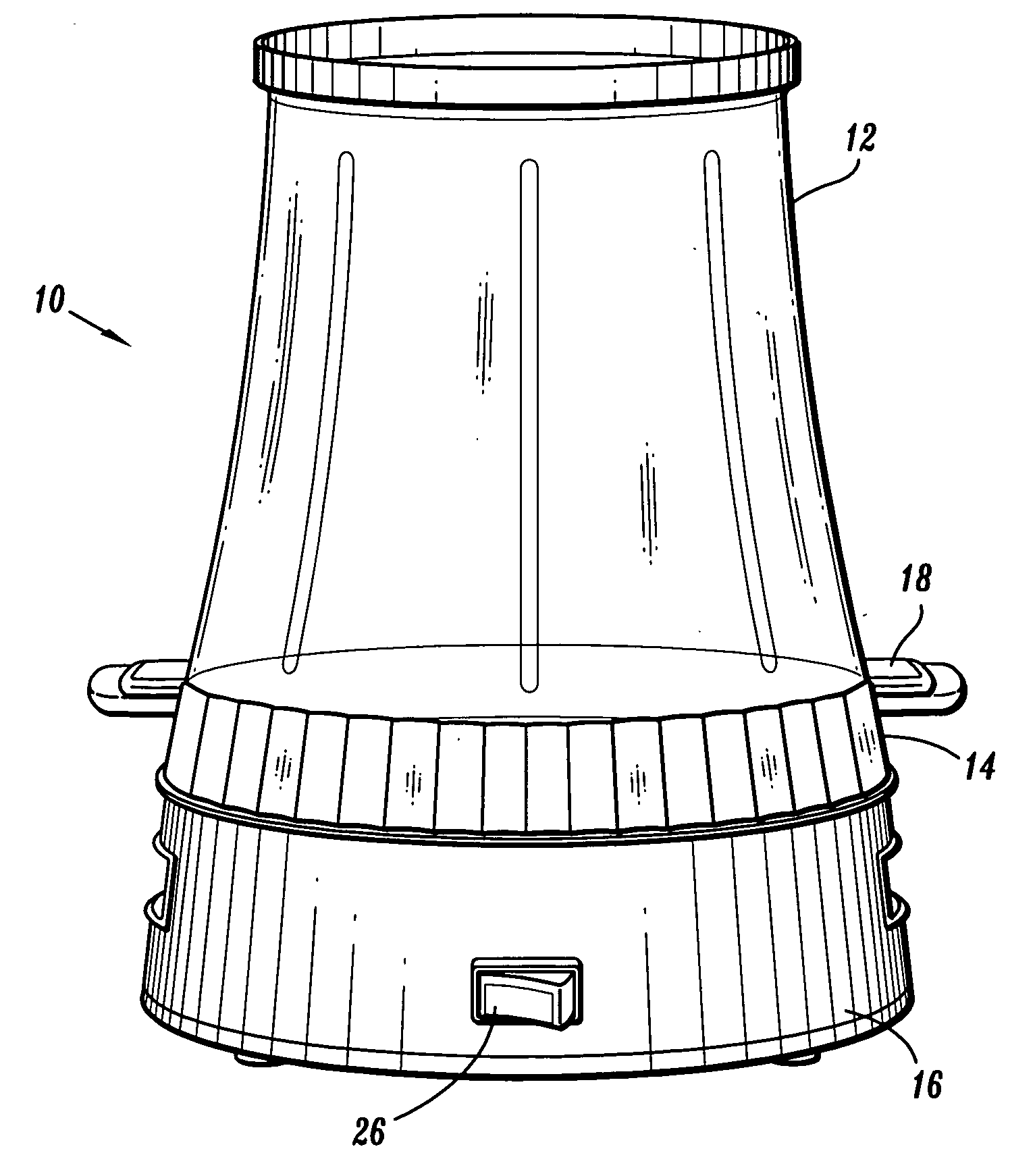
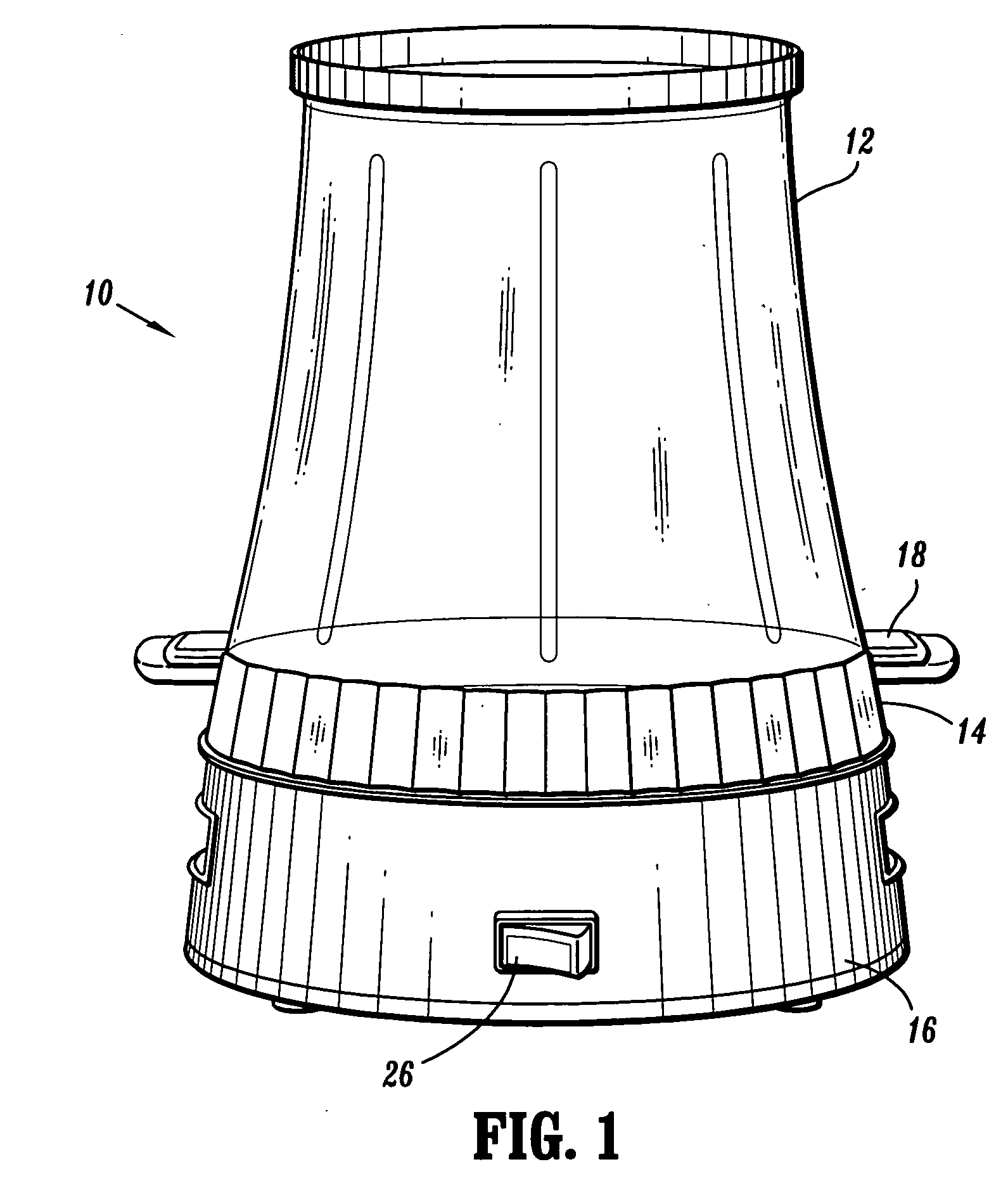
[0014] Referring to FIG. 1, there is shown a popcorn-making device 10 according to the preferred embodiment of the present invention that comprises a bowl 12 attached to a popping plate assembly 14 and a base 16. The base 16 is adapted to rest on a generally flat surface such as a counter or tabletop.

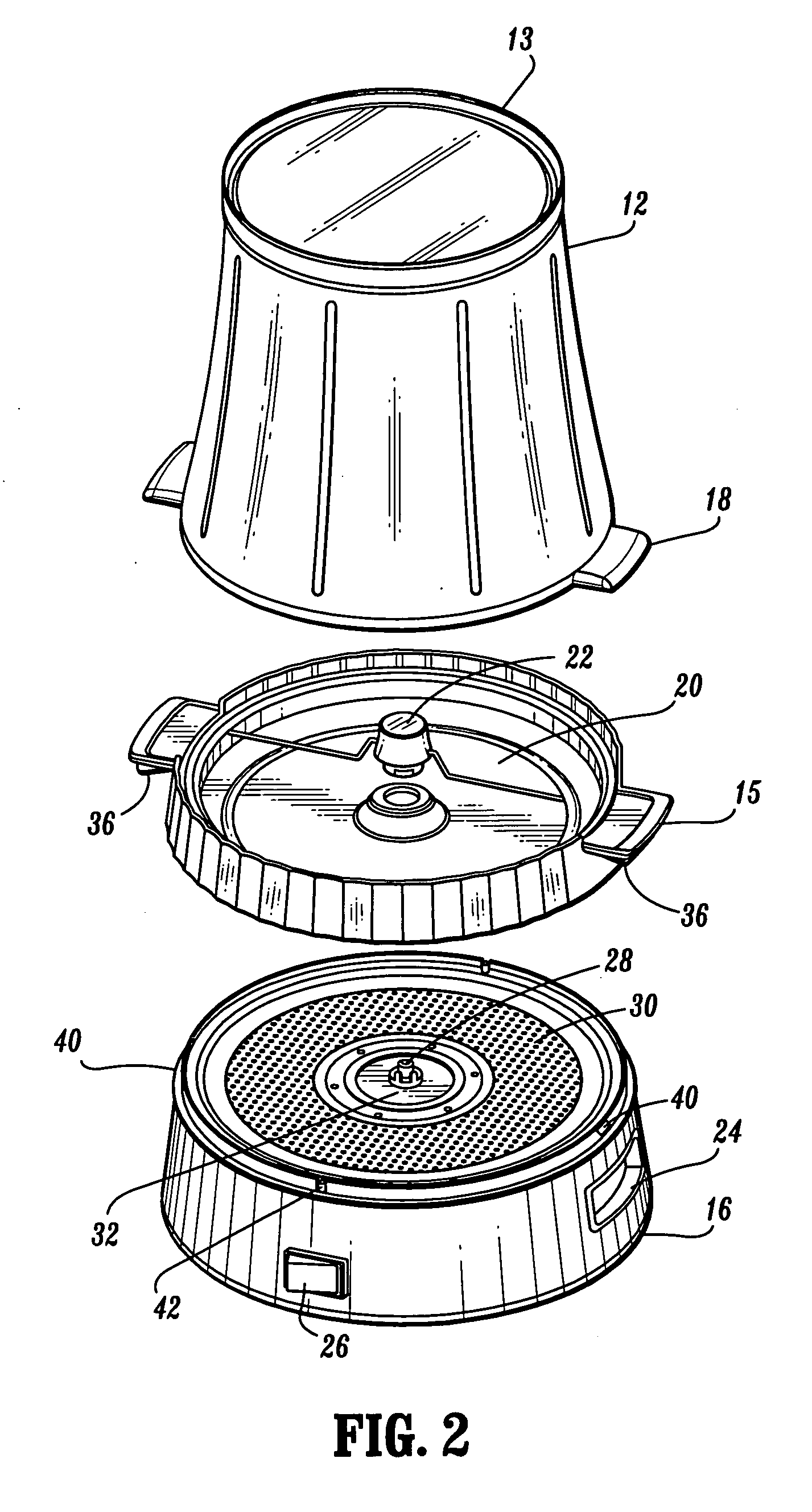
[0015]FIG. 2 shows an exploded view of the popcorn-making device 10. The bowl 12 is used to contain the corn kernels while they are being popped and to act as a serving bowl for the popped kernels during consumption. The bowl 12 can be made from plastic or any other material sufficient to hold the popcorn and withstand the heat necessary to pop the kernels. The top end of the bowl 12 has a raised flange 13. This raised flange 13 assists in preventing excessive heat and condensation from affecting the counter or tabletop. Preferably, the bowl 12 is transparent so that a user may see the kernels as they are being popped. However, the bowl 12 can also be opaque or non-transparent. The bow...


PUM


Abstract

A popcorn-making device comprises a bowl attached to a popping plate assembly and a base. The popping plate assembly can be used to hold and heat corn kernels so that they may be popped. A stirring rod rotates on the heat plate in order keep the kernels moving throughout the popping process. This enables the popcorn maker to require less oil, for a healthier alternative to microwave or other types of popcorn. The popping plate assembly can have a safety interlocking mechanism to enable a user to safely and easily remove and reattach the popping plate assembly to and from the base for washing purposes. The device can have a heater safety mechanism to automatically shut the heater when the popping plate assembly is disengaged from the base. At any time that the popping plate assembly is not properly engaged with the base, the heater will be shut off and the device will not operate.

Description

CROSS-REFERENCE TO RELATED APPLICATIONS [0001] This application claims priority to U.S. Provisional Patent Application Ser. No. 60 / 714,169 filed on Sep. 2, 2005, incorporated herein by reference in its entirety.BACKGROUND OF THE INVENTION [0002] 1. Field of the Invention [0003] The present invention relates to a popcorn maker, and more particularly, to a popcorn maker having a bowl and popping plate that are removable for cleaning purposes, as well as a popcorn maker that enables a user to control the type and amount of corn, oil and flavorings. [0004] 2. Description of Related Art [0005] Popcorn-making devices of various types are known in the art and are used for popping kernels of corn into popcorn. There are various methods for heating the corn kernels, with various ingredients added in the popcorn-making process. However, other known devices do not enable a user to easily remove the components of the device so that they may be washed. Other known devices also do not have an eff...

Claims


Application Information

Patent Timeline
IPC IPC(8): A23L1/18
CPCA23L1/1812A23L7/183
Inventor KERNAN, COLIN M.
Owner CONAIR CORP
Learn More