Flinger disc

a flinger disc and disc body technology, applied in the field of lubrication, can solve the problems of premature wear and component or system failure, premature wear and failure of machine elements, and the diameter of traditional flinger discs is limited, so as to increase the life of lubrication, reduce temperature, and increase the effect of bearing li

Inactive Publication Date: 2006-04-06
TRICO CORP
View PDF53 Cites 2 Cited by
  • Summary
  • Abstract
  • Description
  • Claims
  • Application Information

AI Technical Summary

Benefits of technology

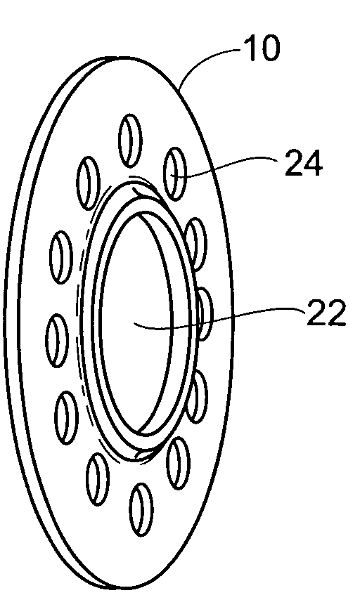
[0013] Also in a preferred embodiment, grooves are molded into the either Viton™ or flexible plastic disc portion at different diameters to allow for flexibility. Scissors can be used to cut out the required diameter and adjust the level of submersion into the oil.
[0014] Perceived advantages of the present invention comprise a reduction in temperature; increased bearing life; increased lubrication life; possibility to run at higher speeds; reduction in required oil level; maintain bearing life while consuming less oil; reduction in energy costs; elimination of contamination by wearing of Oil rings. Additionally, the flinger disc of the present invention advantageously provides: 1) same submersion level in oil as oil rings 2) not sensitive to horizontality; 3) not sensitive to wear and 4) easier assembly and disassembly of pump drive end.

Problems solved by technology

Improper lubrication is likely to lead to premature component wear and component or system failure.
Although this type of lubricator provides reasonable performance in many steady-state operations, multiple variables can create unacceptable operating conditions and lead to premature wear, or even failure, of machine elements.
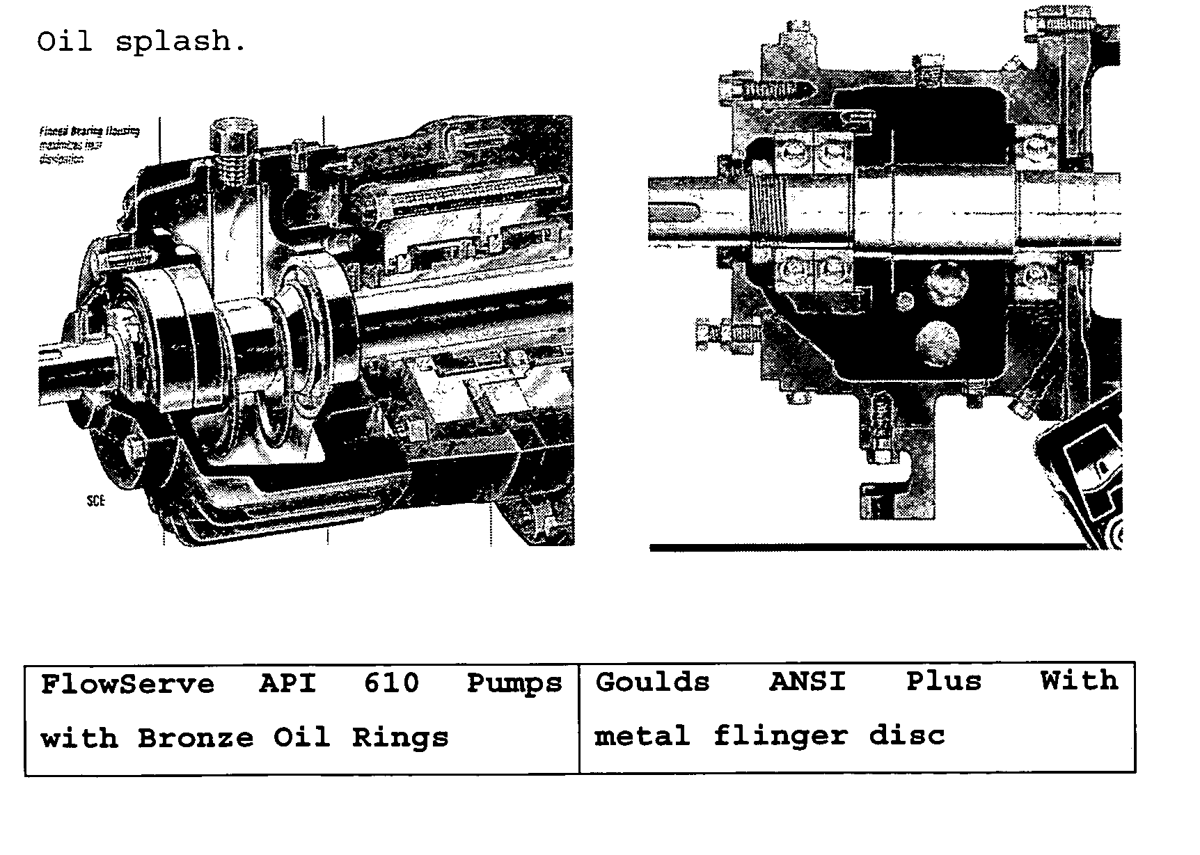
Traditional flinger discs are limited in diameter by the design of the housing.

Method used


Image

  • Flinger disc
  • Flinger disc
  • Flinger disc

Examples


Embodiment Construction

[0018] Although the disclosure hereof is detailed and exact to enable those skilled in the art to practice the invention, the physical embodiments herein disclosed merely exemplify the invention which may be embodied in other specific structure. While the preferred embodiment has been described, the details may be changed without departing from the invention.

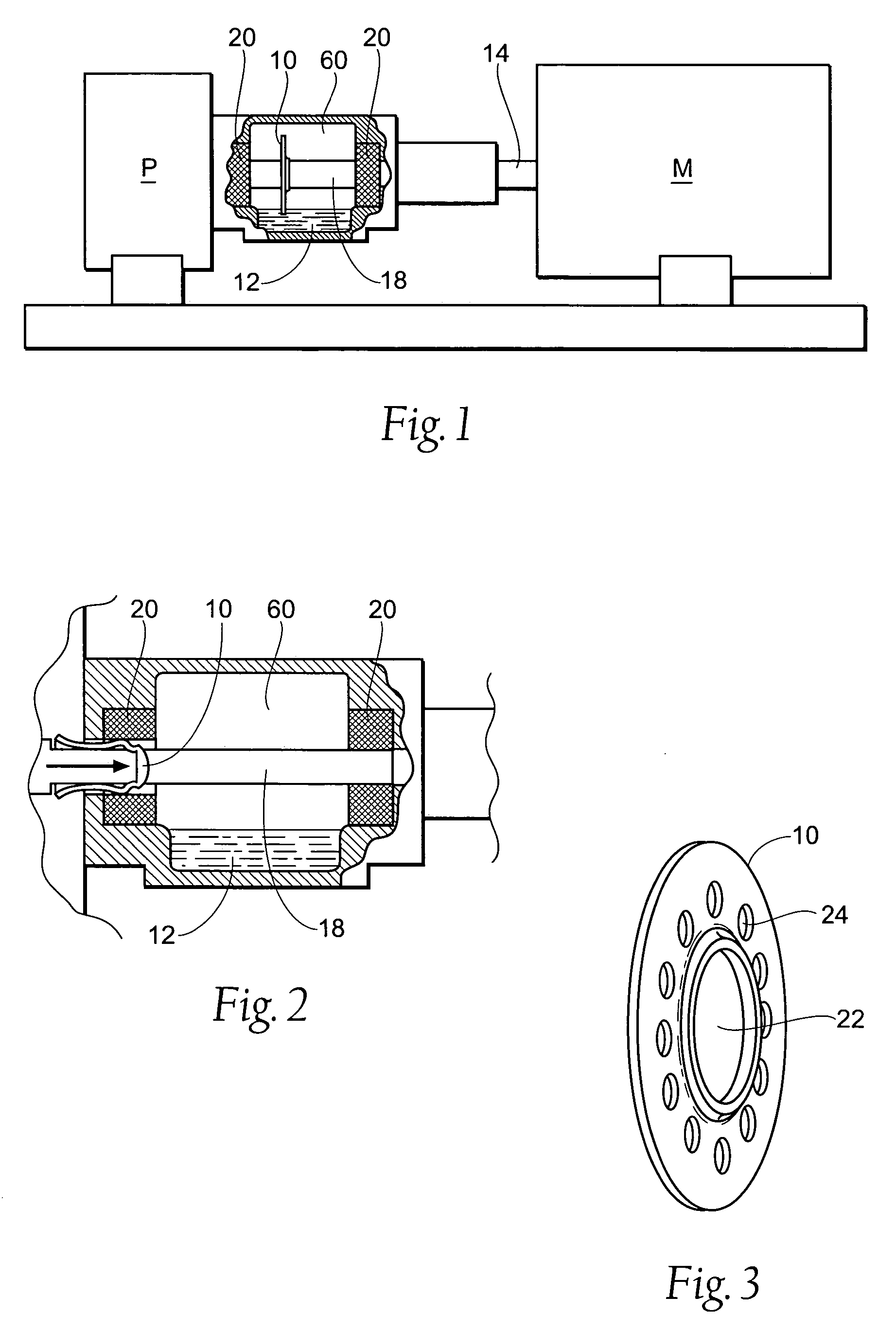
[0019] Referring now to FIG. 1., a side view, with portions broken away, of the workpiece to which the flinger disk of the present invention is advantageously applied is shown, although the invention can be applied in different work environs. In FIG. 1, the workpiece is shown as a centrifugal pump P with a motor M. The invention provides an optimal lubrication condition to machine element or bearings 20 by providing a flinging of the lubricant 12, such as oil. In FIG. 1, the bearings 20 are viewed from the side, with their front profile generally doughnut shaped. The lubricant 12 is contained within a fluid reservoir, or bearin...


PUM

PropertyMeasurementUnit
outer diameteraaaaaaaaaa
flexibilityaaaaaaaaaa
frictionaaaaaaaaaa

Abstract

To achieve proper lubrication, a bearing housing or reservoir is filled with a predetermined amount of lubricant. When the machine, of which a bearing is a component, is operated, a flexible flinger disc provides proper lubrication by disturbance of the lubricant.

Description

BACKGROUND OF THE INVENTION [0001] Lubrication is an important aspect of maintaining machinery in proper operating condition. Machine elements such as bearings, journals, shafts, and joints require proper lubrication between their moving surfaces to decrease friction, prevent contamination, reduce wear and dissipate heat. Improper lubrication is likely to lead to premature component wear and component or system failure. [0002] When determining the optimal lubrication between moving machine elements, many factors should be considered. These factors include the mode of operation of the machine, the type of machine element to be lubricated, the environment of the machine, the operating speed of the machine, the lubricant's viscosity, the lubricant's temperature, the lubricant's ingredients, and the lubricant's condition. [0003] Prior art lubricators, such as the TRICO OptoMatic oiler, supply a constant level of lubricant within a lubricant reservoir to a machine element. The lubricant ...

Claims


Application Information

Patent Timeline
Patent Type & Authority Applications(United States)
IPC IPC(8): B32B3/02
CPCF16C33/103Y10T428/218F16N7/22
Inventor BLOCH, HEINZ P.THOMAS, ROJEAN M.FREELAND, DAN E.MALINOWSKI, JEFF T.
Owner TRICO CORP
Why Eureka
Try Eureka