Self-erecting structure for rod-shaped member and method of producing rod-shaped member having self-erecting structure

Inactive Publication Date: 2007-03-15
HUH GENE
View PDF3 Cites 18 Cited by
  • Summary
  • Abstract
  • Description
  • Claims
  • Application Information

AI Technical Summary

Benefits of technology

[0013] In a self-erecting structure for a rod-shaped member according to a sixth aspect of the present invention, the mount surface in the first and third to fifth aspects is arranged to be capable of accommodating a first rod-shaped member and a second rod-shaped member side-by-side and is formed with a first erecting action surface and a second erecting action surface for the first and second rod-shaped members, respectively. The first and second erecting action surfaces are spaced from each other to such an extent that when the erecting operation parts of the first and second rod-shaped members are positioned on the first and second erecting action surfaces, respectively, the magnet of the first rod-shaped member and the magnet of the second rod-shaped member do not attract each other. If the two rod-shaped members are placed on the mount surface in a state where the magnet of the first rod-shaped member and the magnet of the second rod-shaped member are close in position to each other, the magnets of the two rod-shaped members may undesirably attract each other. In such a

Problems solved by technology

On such an occasion, the user may undesirably drop a brush or the like accommodated in the container owing to vibration or other movement occurring when he or she opens the lid of the container.
In a case where

Method used


Image

  • Self-erecting structure for rod-shaped member and method of producing rod-shaped member having self-erecting structure
  • Self-erecting structure for rod-shaped member and method of producing rod-shaped member having self-erecting structure
  • Self-erecting structure for rod-shaped member and method of producing rod-shaped member having self-erecting structure

Examples


Embodiment Construction

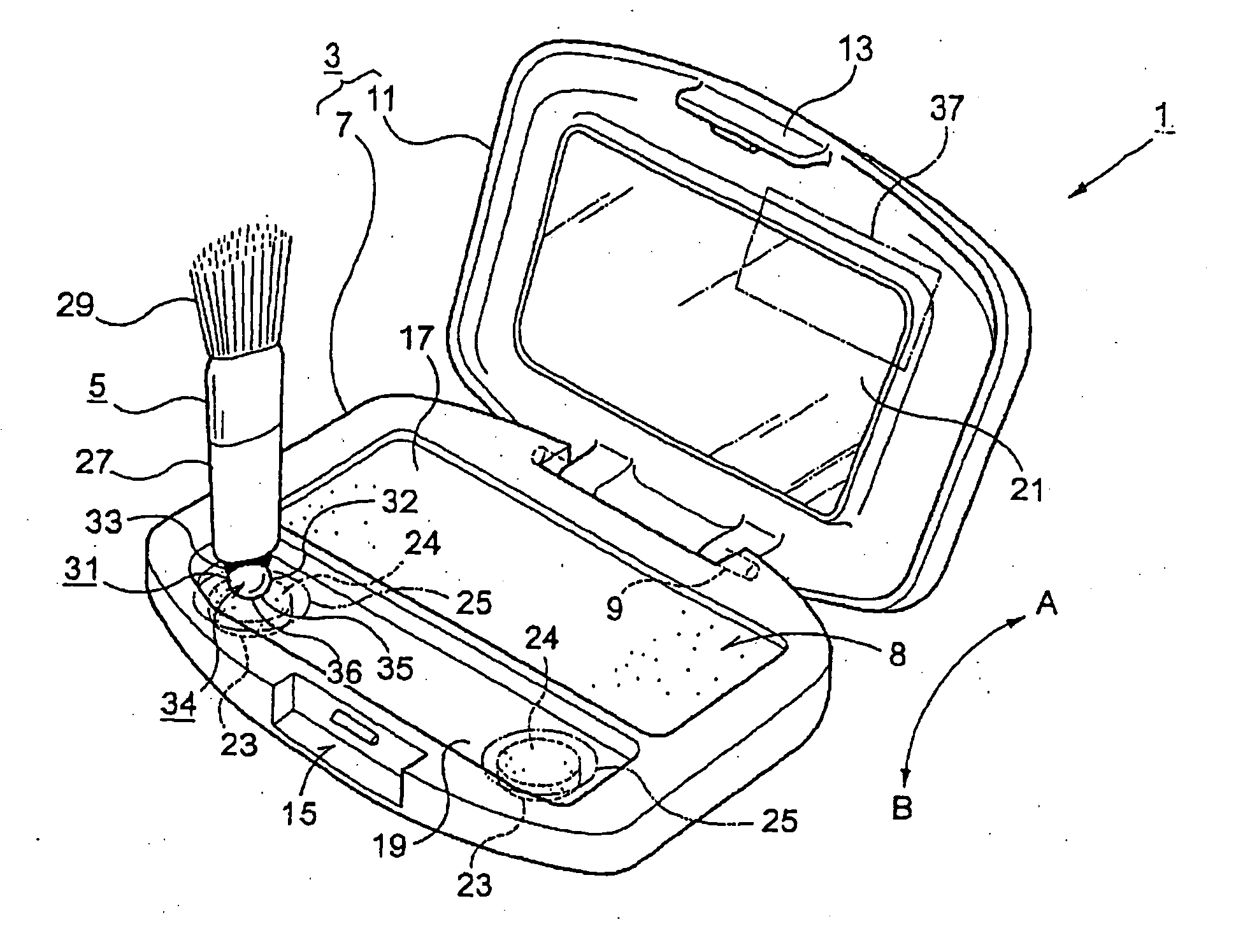
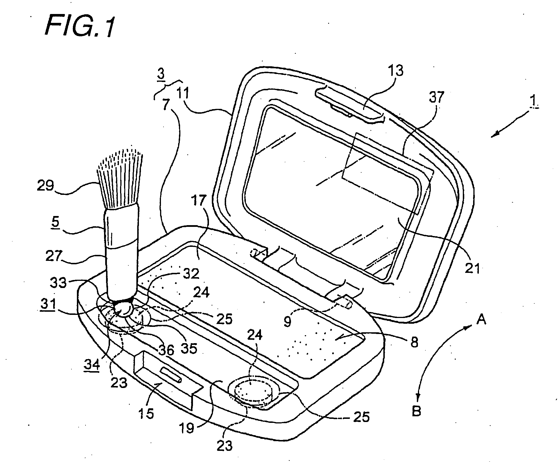
[0026] Embodiments of the invention in this application will be described below with reference to the accompanying drawings. FIG. 1 is a perspective view showing the way in which a self-erecting structure for a rod-shaped member according to the present invention is applied to a cosmetic compact case 1. The cosmetic compact case 1 is mainly used by a woman to put on makeup when she is away from home or on other occasion. The cosmetic compact case 1 has a case body 3 corresponding to the container and a makeup brush 5 corresponding to the rod-shaped member.

[0027] The case body 3 has a base 7 and a lid 11 connected to the base 7 pivotably about a pivot shaft 9. When in use, the lid 11 is pivoted through about 90 degrees as indicated by the arrow A in FIG. 1 to open the top side of the base 7, that is, an open part 8. When not in use, the lid 11 is pivoted in the direction indicated by the arrow B, and a latch piece 13 formed on the lid 11 is snap-fastened to a latch lock part 15 form...


PUM


Abstract

The present invention provides a self-erecting structure for a rod-shaped member, e.g. a brush, which enables the rod-shaped member to be readily taken out from an associated container while satisfying the demand that the rod-shaped member should be prevented from easily dropping from the container, and also provides a method capable of readily producing a rod-shaped member having such a structure.
A rod-shaped member 5 has an erecting operation part 34 formed with a rolling surface 32 and an erection support surface 35. A first magnet 31 is provided in the vicinity of the erection support surface in a state where a first magnetic pole of the first magnet 31 faces toward one end of the rod-shaped member 5. Magnetic force from the first magnetic pole acts on the erection support surface. A second magnet 23 or a ferromagnetic material is provided in the vicinity of an erecting action surface 25. The second magnet has a second magnetic pole opposite in polarity to the first magnetic pole. The second magnetic pole faces upward so that magnetic force from the second magnetic pole acts on the erecting action surface. The rod-shaped member is constantly urged to pivot in the erecting direction by magnetic attraction force between the two magnets so that the rod-shaped member is automatically shiftable from a lying position to an erect position. A lid 11 of the container has an erection restraining part 37 capable of holding the rod-shaped member in the lying position on a mount surface 19 against the urging force when the lid 11 is closed.

Description

TECHNICAL FIELD [0001] The present invention relates to a structure for allowing a rod-shaped member, e.g. a makeup brush, to erect automatically, and also pertains to a method of producing such a rod-shaped member. BACKGROUND ART [0002] When makeup brushes, for example, are stored in associated containers, they are generally accommodated side-by-side in accommodating portions of the containers in their lying position. Containers for accommodating makeup brushes, etc. tend to be made small and thin for carrying convenience. When using a makeup brush or the like, the user opens the lid of the associated container and picks up the desired brush or the like, which is in its lying position, with his or her fingers. On such an occasion, the user may undesirably drop a brush or the like accommodated in the container owing to vibration or other movement occurring when he or she opens the lid of the container. In a case where the rod-shaped member accommodated is a makeup brush or tip, if i...

Claims


Application Information

Patent Timeline
IPC IPC(8): A45D33/24A45D33/00A45D40/22A45D40/24
CPCA45C11/34A45D40/24A45D40/22A45D33/008
Inventor HUH, GENE
Owner HUH GENE
Why Eureka
Try Eureka