Speed shift arrangement for work vehicle

a technology for work vehicles and shift levers, which is applied in the direction of mechanical control devices, process and machine control, instruments, etc., can solve the problems of difficult to see display means and inability to make full use of the shift lever construction, and achieve convenient forward and reverse operation of the vehicle, convenient access, and easy to see by operators

Active Publication Date: 2007-03-15
KUBOTA LTD
View PDF22 Cites 12 Cited by
  • Summary
  • Abstract
  • Description
  • Claims
  • Application Information

AI Technical Summary

Benefits of technology

[0004] The object of this invention is to provide a speed shift arrangement for a work vehicle, which enables a shifting operation to be carried out while promptly determining a speed state of a propelling speed change device while facilitating a forward and reverse drive switching of a vehicle body.
[0015] This arrangement allows the speed change lever to be located at a position conveniently accessed and easily seen by an operator. It also facilitates a forward and reverse operation of the vehicle simply by operating the speed change lever along one fore and aft channel.

Problems solved by technology

In this type of tractor, however, even if display means is provided for showing the speed state of the propelling speed change device, the display means may be difficult to see.
It is impossible to make full use of the construction having the shift lever disposed laterally of the steering stem.

Method used


Image

  • Speed shift arrangement for work vehicle
  • Speed shift arrangement for work vehicle
  • Speed shift arrangement for work vehicle

Examples


first embodiment

[0039] this invention will be described first.

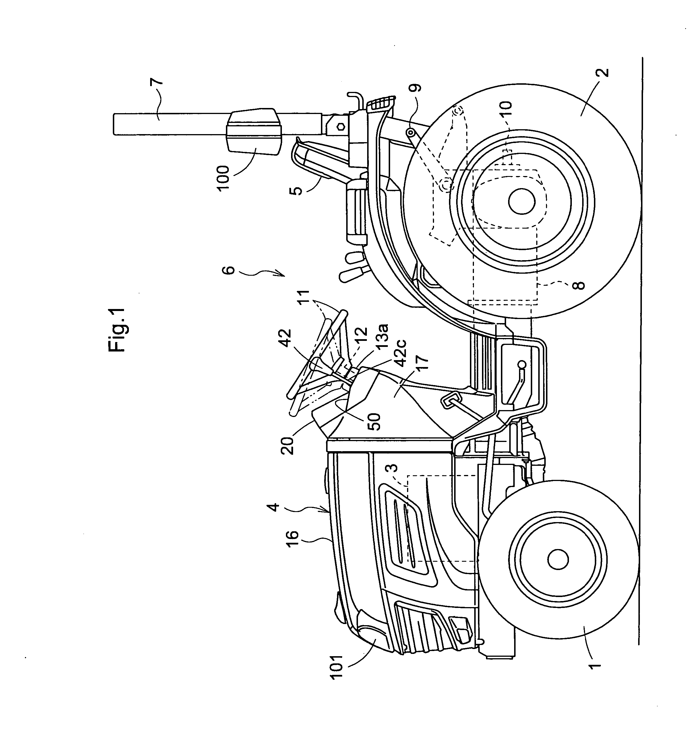
[0040] As shown in FIG. 1, a tractor (an example of a work vehicle) includes a self-propelled vehicle body having a pair of right and left dirigible front drive wheels 1, a pair of right and left rear drive wheels 2, a motor section 4 with an engine 3 mounted on a front portion of the vehicle body, a driving platform 6 with a driver's seat 5 disposed adjacent a rear end of the vehicle body, and a rollover protection frame 7 provided adjacent the rear of the driver's seat 5. A transmission case 8 forms a rear portion of a body frame of the vehicle body. A pair of right and left lift arms 9 are arranged above the transmission case 8 to be vertically swingable by a hydraulic cylinder (not shown) mounted in the transmission case 8. A power takeout shaft 10 projects from a rear wall of the transmission case 8,

[0041] This tractor can form various types of riding work machines with various types of working implements connected thereto to be ve...

second embodiment

[0072] Next, this invention will be described.

[0073] In this embodiment, the operating direction of the shift lever is different from the operating direction in the first embodiment.

[0074]FIG. 12 shows a side elevation of a tractor which is one example of working vehicles. The tractor includes a front frame 101, and a transmission case 102 serving also as a rear frame, constituting a body frame 103. This is a four-wheel drive tractor in which power of an engine 104 mounted with vibration isolation on a front portion of the body frame 103 is transmitted through a gear type propelling speed change device 105 mounted in the transmission case 102 to right and left front wheels 106 and rear wheels 107.

[0075] The transmission case 102 has, arranged on the rear portions thereof, a pair of right and left lift arms 108 vertically swingable by a hydraulic lift cylinder (not shown) mounted in the transmission case 8, and a power takeout shaft 109 for taking out engine power.

[0076] A driving...


PUM


Abstract

A work vehicle comprises a plurality of wheels; a propelling speed change device supported by the plurality of wheels and having at least one forward travel position and a reverse travel position with substantially the same speed reduction ratio as the forward travel position; a steering wheel for steering at least one of the plurality of wheels; a steering wheel support shaft for supporting the steering wheel; a speed change lever located in a position laterally of the steering wheel support shaft and operatively connected to the propelling speed change device to operate the propelling speed change device; a speed change lever guide for guiding the speed change lever, the guide including: a plurality of fore and aft channels extending substantially in the fore and aft direction of the work vehicle; a communication channel extending between the plurality of fore and aft channels; wherein one of the plurality of the fore and aft channels has a first lever position corresponding to the forward travel position and a second lever position corresponding to the reverse travel position.

Description

BACKGROUND OF THE INVENTION [0001] The present invention relates to a speed shift device for a work vehicle such as a tractor. [0002] The above shifting apparatus includes a shift lever is disposed to be rockable in a position laterally of a steering stem, so that the driver may, while looking in a traveling direction, operate the shift lever to change running speed, and that the shift lever hardly obstructs the driver boarding or alighting from a driving platform. A known shifting apparatus of this type is disclosed in Unexamined Utility Publication S60-103026 (pages 4 and 5, FIG. 3), for example. [0003] A desired speed state may be obtained reliably by carrying out a shift operation appropriately while recognizing or confirming a current speed state of a propelling speed change device, or what speed state the speed change device is to switch. In this type of tractor, however, even if display means is provided for showing the speed state of the propelling speed change device, the d...

Claims


Application Information

Patent Timeline
Patent Type & Authority Applications(United States)
IPC IPC(8): B60K17/00
CPCB60K20/08B60Y2200/221F16H59/02Y10T74/20116F16H2059/0256Y10T74/20171F16H59/042B60K20/00
Inventor YANAGIHARA, KATSUMISHOEN, SHIGEOHIRAKAWA, KENKICHIKOMINE, TAKAHIRONAKAMURA, TADASHI
Owner KUBOTA LTD
Why Eureka
Try Eureka