Image generating process

a technology of image generating and image, applied in the field of image generating process, can solve the problems of difficult to apply, difficult to print, high cost of large printed hoardings, etc., and achieve the effect of large images, good printing base and short tim

Inactive Publication Date: 2007-03-15
IDEEUNDTECHN
View PDF3 Cites 10 Cited by
  • Summary
  • Abstract
  • Description
  • Claims
  • Application Information

AI Technical Summary

Benefits of technology

[0046] The apparatus can advantageously be fitted interchangeably to a piste groomer, with the emission apparatus comprising a printing device with a lateral extent which corresponds at least approximately to the lateral extent of the piste groomer. The printing device can be fitted to an existing rear fitting on the piste groomer. Piste groomers are normally available in winter sports regions so that there is no need to procure any additional, expensive vehicle to carry out the method according to the invention. The operation of vehicles such as these is also entrusted to the local authorities. Piste groomers are wide so that large images can also be produced in a short time with one printing device which essentially covers at least their width. It is normal to retrofit piste groomers with special tools, for example rollers, blades, etc. Various rear fittings are thus available, inter alia, in particular track cutting machines or snow clearing machines, trailer units, track machines or smoothers. The fact that the printing device can be fitted to an already existing rear fitting such as this offers the advantage that the already existing attachment to the piste groomer can still be used, and need not be provided once again. The rear fitting can also prepare the snow surface so as to produce a good printing base.
[0047] In particular, as an alternative, smaller images can also be produced on snow surfaces by snowmobiles. These are also normally available in winter sports regions. In comparison to a piste groomer, they are also more flexible in use and, particularly in the case of relatively small images, can be used more easily, better and quicker.
[0048] The apparatus can also be designed such that it does not interact with an existing rear fitting. In this case, it advantageously has means for fitting the apparatus to a piste groomer, which interact with normal attachment devices for special tools (such as rollers, blades etc.). The means for fitting are thus preferably matched to these attachment devices, so that the apparatus can be retrofitted easily. Snowmobiles often also have usable attachment means, such as trailer couplings.

Problems solved by technology

Guard nets at the edge of the pistes are, for example, generally designed for technical reasons such that printing is not possible in a manner which would allow advertising messages to be recognized from a relatively long distance.
However, these often lead to impediments and can generally be installed only at points where they can scarcely be seen.
However, these can likewise be seen only with difficulty and can be applied only at points which are away from the piste and the viewer area.
Furthermore, large printed hoardings are expensive and require complex anchorages against the influence of wind.

Method used


Image

  • Image generating process
  • Image generating process
  • Image generating process

Examples


first embodiment

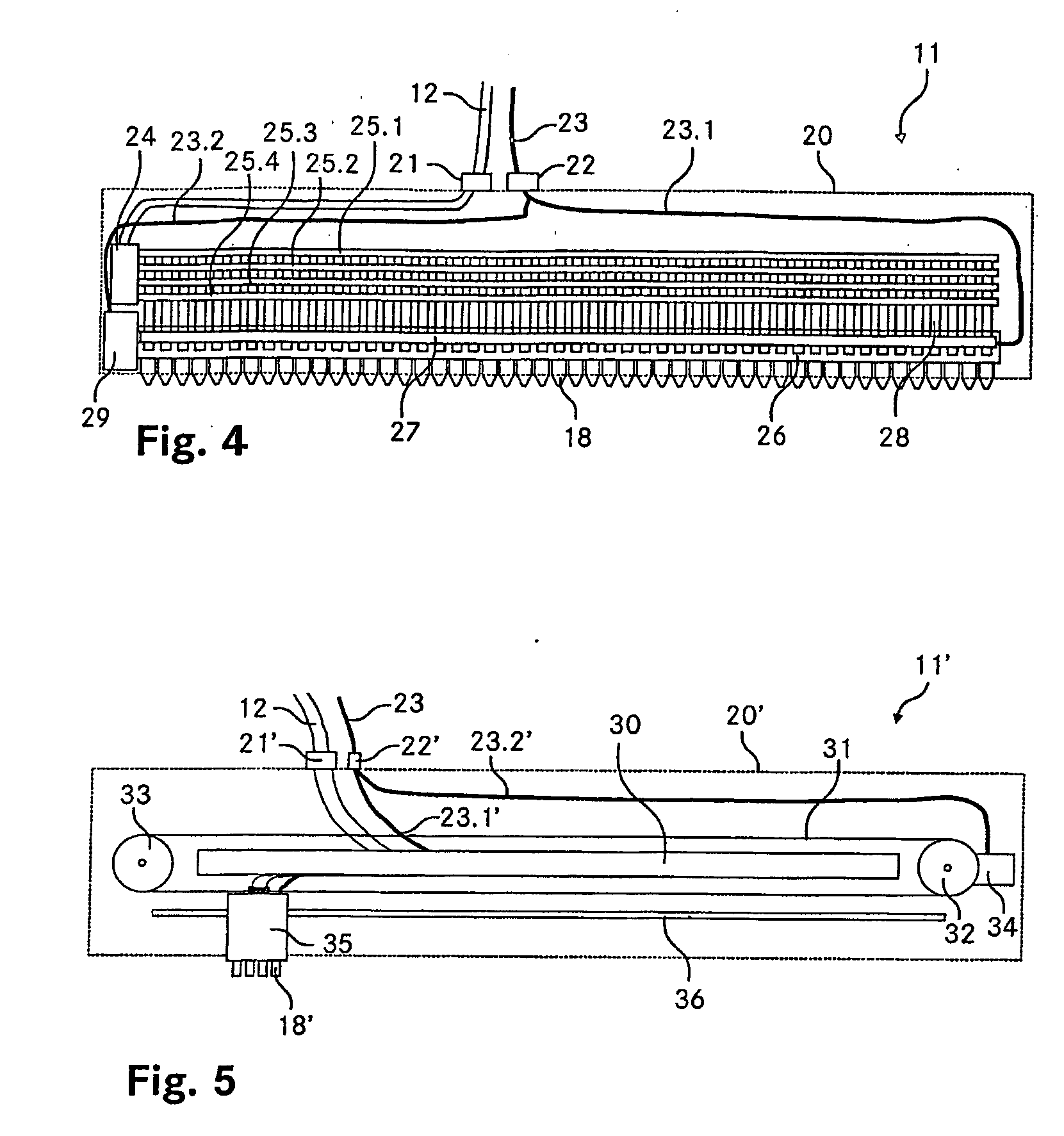
[0058]FIG. 4 shows a schematic illustration of a spraying apparatus according to the invention, viewed from the side;

second embodiment

[0059]FIG. 5 shows a schematic illustration of a spraying apparatus according to the invention, viewed from the side;

[0060]FIGS. 6A, B show a first arrangement of spraying nozzles for a spraying apparatus according to the invention;

[0061]FIGS. 7A, B show a second arrangement of spraying nozzles for a spraying apparatus according to the invention;

[0062]FIGS. 8A, B show a third arrangement of spraying nozzles for a spraying apparatus according to the invention;

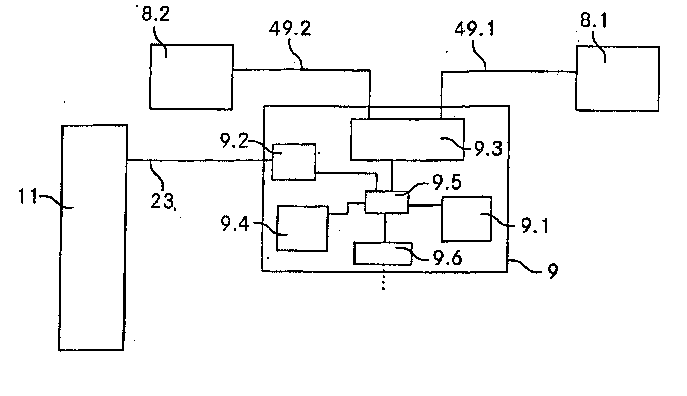
[0063]FIG. 9 shows a schematic illustration of the circuit of an apparatus according to the invention;

[0064] FIGS. 10A-C show a schematic illustration of the method according to the invention;

[0065]FIG. 11A shows a schematic illustration of an inscription, produced using the method according to the invention, seen from a predetermined observation position; and

[0066]FIG. 11B shows a schematic illustration of the inscription, sprayed onto a snow surface.

[0067] Fundamentally, identical parts are provided with the same referen...


PUM


Abstract

In a method for generating an image on a land surface by means of an applicator (11), the applicator (11) is first moved on a first place on the land surface and the position of the applicator (11) is determined. Depending on the thus determined position, a marking substance is then applied to the land surface. Finally, the applicator (11) is moved to another place on the land surface. A device for generating an image on a land surface comprises locating means (8.1, 8.2, 9) for locating a position of the device, application means (11) for applying a marking substance to the land surface and control means (9) for automatically controlling the application means (11) depending on the thus determined position.

Description

TECHNICAL FIELD [0001] The invention relates to a method in order to produce an image on a land surface by means of an emission apparatus, and to an apparatus for production of an image on a land surface. PRIOR ART [0002] It has been known for a long time for strips in sports stadiums which, for example, surround a field of play for football or ice hockey, to be provided with inscriptions, logos and images, predominantly of an advertising nature. This advertising often reaches not only the public who are attending the game but, by means of television transmissions, a far greater group of people. [0003] In the case of skiing and other winter sports events, which are likewise often broadcast by television, printable strips can be applied only to a restricted extent. Guard nets at the edge of the pistes are, for example, generally designed for technical reasons such that printing is not possible in a manner which would allow advertising messages to be recognized from a relatively long ...

Claims


Application Information

Patent Timeline
Patent Type & Authority Applications(United States)
IPC IPC(8): B64D1/18G09F19/00G09F19/22
CPCG09F19/22G09F19/00B60W2300/43B60K31/00
Inventor SCHROTER, GERD ALWIN
Owner IDEEUNDTECHN
Why Eureka
Try Eureka