Injection valve and method of making orifice

Inactive Publication Date: 2007-03-15
HITACHI LTD
View PDF12 Cites 12 Cited by
  • Summary
  • Abstract
  • Description
  • Claims
  • Application Information

AI Technical Summary

Benefits of technology

[0022] According to the present invention, an injection

Problems solved by technology

According to such a hole processing, as the injection hole is tapered, it is difficult to obtain a cylindrical orifice.
Further, upon drawing, as the orifice is taper-deformed, the injection hole precision upon perforation cannot be maintained without difficulty.
Accordingly, it is extremely difficult to obtain a μm-order precision inject

Method used


Image

  • Injection valve and method of making orifice
  • Injection valve and method of making orifice
  • Injection valve and method of making orifice

Examples


embodiment 1

[Embodiment 1]

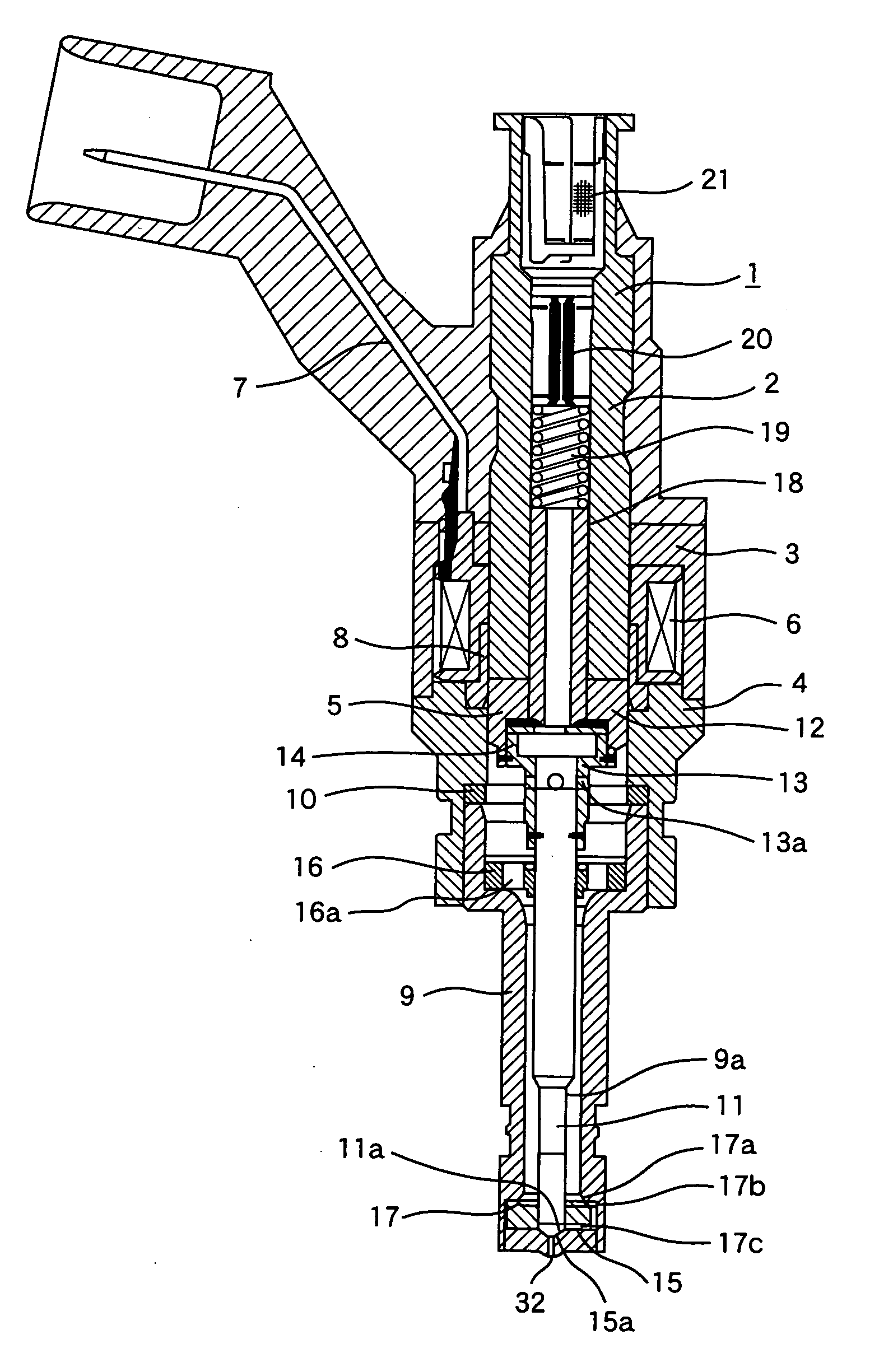
[0032]FIG. 1 is a longitudinal sectional view showing the entire structure of an injection valve according to an embodiment of the present invention.

[0033] An injection valve 1 has a magnetic circuit including a stationary core 2, a yoke 3, a housing 4 and a movable element 5, a coil 6 for exciting the magnetic circuit, and a terminal bobbin 7 to energize the coil 6. A seal ring 8 is interposed between the core 2 and the housing 4 so as to prevent inflow of fluid such as fuel into the coil 6.

[0034] Valve parts are positioned in the housing 4. The movable element 5, a nozzle body 9 and a ring 10 for regulating a stroke of the movable element 5 are arranged. The movable element 5 is a combination of a valve needle 11 and a movable core 12 with a joint 13. A plate 14 for suppressing rebound of the movable element 5 at valve closing, in cooperation with a pipe 18, is provided between the movable core 12 and the joint 13.

[0035] The housing 4 and the nozzle body 9 are joi...

embodiment 2

[Embodiment 2]

[0056]FIG. 7 shows an example where six orifices 54, 55, 56, 57, 58 and 59 as plural orifices are made in an orifice plate 50. The downstream side of the orifice plate 50 has a concave portion formed by an inner wall 52 and an inner bottom 53. A spherical projection 51 is formed in the area of an inner bottom 53.

[0057] In the spherical projection51, the respective orifices 54, 55 , 56, 57, and 58 are opened in different directions, and flat surface portions 54a, 55a, 56a, 57a, 58a and 59a around the respective orifices are formed at right angles to the axes of the respective orifices. In other words, the orifices 54, 55, 56, 57, 58 and 59 are made at right angles to the respective flat surface portions, and outlets of the respective orifices are opened in the respective flat surface portions.

[0058] In the flat surface portions 54a, 55a, 56a, 57a, 58a and 59a, as long as portions where the orifices 54, 55, 56, 57, 58 and 59 are opened are flat surfaces at minimum, the...

embodiment 3

[Embodiment 3]

[0060]FIG. 8 shows an example where six orifices 64, 65, 66, 67, 68 and 69 as plural orifices having different lengths from to each other are made in an orifice plate 60. The downstream side of the orifice plate 60 has a concave portion formed by an inner wall 62 and an inner bottom 63. A spherical projection 61 is formed in the area of an inner bottom surface 63.

[0061] The respective orifices 64, 65, 66, 67, 68 and 69 are opened in different directions, and the outlets of the orifices are positioned in the respective hollows provided in the area of the spherical projection 61. The inner bottoms of the hollows are respectively formed with flat surface portions 64a, 65a, 66a, 67a, 68a and 69a. The flat surface portions 64a, 65a, 66a, 67a, 68a and 69a are formed at right angles to the axes of the respective orifices in the area of the spherical projection 61. The orifices 64, 65, 66, 67, 68 and 69 are made at right angles to the respective flat surface portions 64a, 65a...


PUM

PropertyMeasurementUnit
Fractionaaaaaaaaaa
Lengthaaaaaaaaaa
Areaaaaaaaaaaa

Abstract

An injection valve has a nozzle body, a valve needle positioned in the nozzle body, an actuator for actuating the valve needle, and an orifice plate fixed at an end of the nozzle body. The orifice plate has a valve seat for cooperate with the valve needle and an orifice for injecting a fluid. The orifice plate is provided with a projection having a convex-curved surface on an orifice outlet side of the orifice plate. A flat surface portion is formed in the area of the convex-curved surface, and the outlet of the orifice is located in the flat surface portion.

Description

CLAIM OF PRIORITY [0001] The present application claims priority from Japanese application serial No. 2005-264572 filed on Sep. 13, 2005, the content of which is hereby incorporated by reference into this application. [0002] 1. FIELD OF THE INVENTION [0003] The present invention relates to an injection valve for injecting a fluid, and more particularly, to an orifice for determining a flow rate, an orifice making method and an injection valve using the orifice. [0004] 2. BACKGROUND OF THE INVENTION [0005] In fuel injection valves, conventional art where an orifice (injection hole) is provided in spherical projection by press working is disclosed in Japanese Patent Laid-Open No. Hei 7-63140. The injection hole is formed by making an injection hole in a flat plate by press working or the like and by drawing a peripheral portion of the injection hole in a dome shape. [0006] Further, as an processing method of deflected orifice in nozzle body manufacturing, press working disclosed in Ja...

Claims


Application Information

Patent Timeline
IPC IPC(8): F02M61/00
CPCB21J5/10B21J9/04F02M61/12Y10T29/49298F02M61/168F02M61/1853F02M61/162
Inventor GUNJI, KENICHIKAWAHARA, KEIJISHIMIZU, SHUICHISEKINE, ATSUSHINAKANO, MASAFUMI
Owner HITACHI LTD
Why Eureka
Try Eureka