
Monitoring an industrial communication network

a communication network and monitoring technology, applied in the field of distribution control systems, can solve the problems of affecting the operation of the substation, so as to achieve the effect of reducing the number of eds

Inactive Publication Date: 2007-03-15
ABB TECH AG
View PDF3 Cites 16 Cited by
  • Summary
  • Abstract
  • Description
  • Claims
  • Application Information

AI Technical Summary

Problems solved by technology

In industrial communication networks of distributed control systems, reliability or availability is a key issue, because a failing communication network generally entails an interruption of the controlling process, which might lead to a shut down of the controlled industrial process.
A reliable SA system is typically required to continue to be operable even if a component fails, i.e. a single point of failure that causes the substation to become inoperable is unacceptable.
A failure of a component of the SA communication network, due to e.g. a loss of a communication port caused by a failing diode for a fibre optic link, can result in the loss of access to the complete substation, one single bay or only one ED.
However, opto-electrical star-type couplers working exclusively with electro-optical conversion on a physical level, Ethernet hubs working exclusively with electrical connections, as well as all interconnecting physical lines, are passive components deprived of any intelligence or programmability.
However, the particular data transmitted is often device-specific and can only be interpreted correctly by communication experts.
In addition, and unless supplemental intelligence is provided for monitoring passive or non-intelligent components, a failure of the latter cannot be identified this way.

Method used


Image

  • Monitoring an industrial communication network
  • Monitoring an industrial communication network

Examples


Embodiment Construction

[0007] It is therefore an objective of the invention to identify failed components of an industrial communication network without reverting to a dedicated communication protocol. It is a further objective of the invention to identify failed passive components without the need for additional devices supervising the latter. These objectives are achieved by a method of as well as a computer program and system for monitoring an industrial communication network as claimed in claims 1, 7 and 8, respectively. Further preferred embodiments are evident from the dependent patent claims.

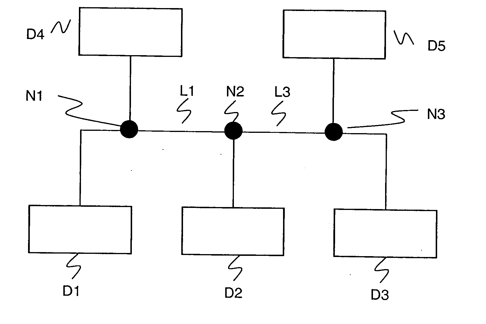
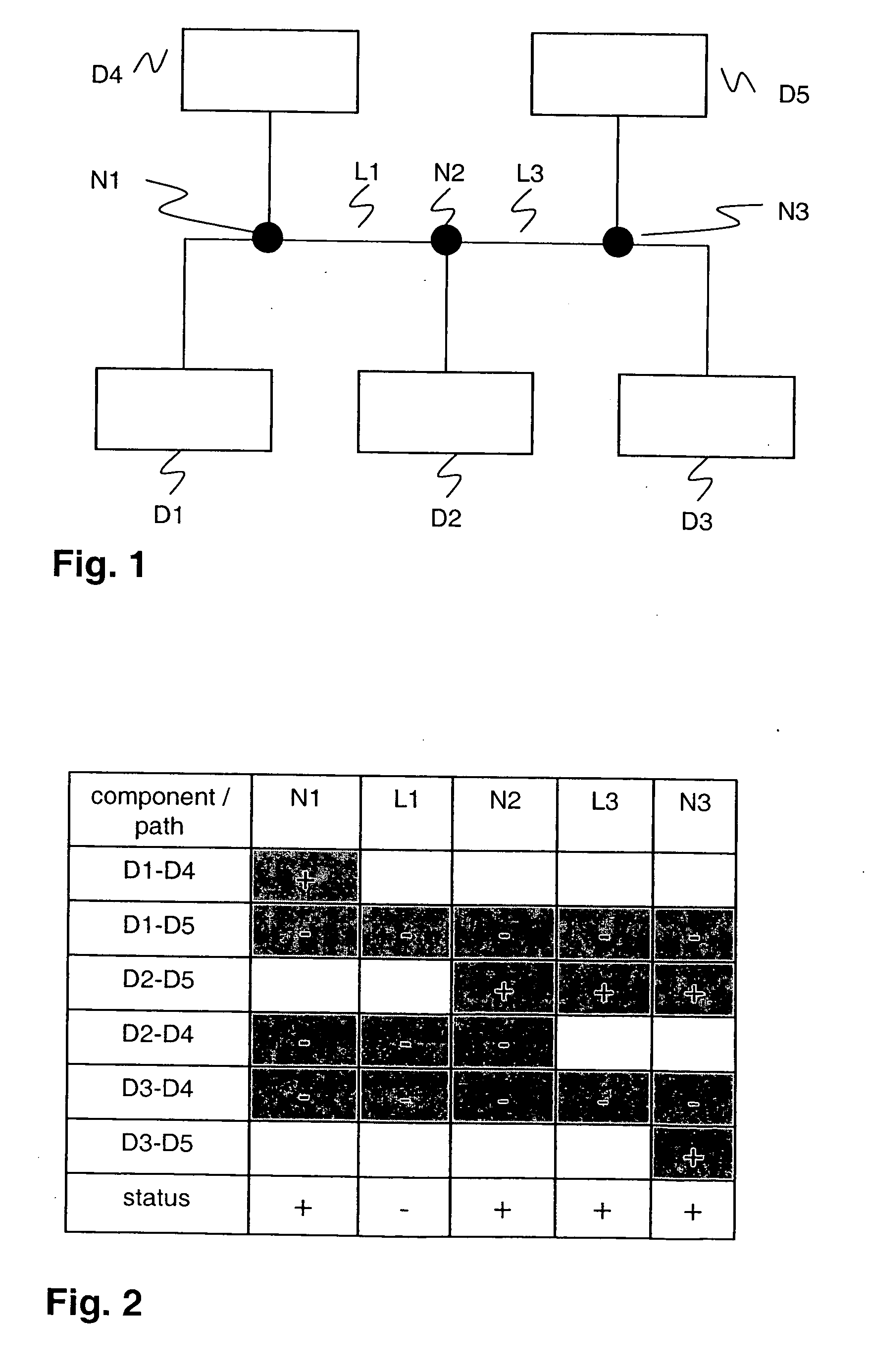
[0008] According to the invention, a limited number of all the communication paths constituting the communication network are supervised, wherein each of the supervised paths includes a distinct set of network components and is delimited by two end-devices. A failure status or operating status of each communication path is determined and reported. Any network component that is part of an operating path is itse...


PUM


Abstract

The present invention is concerned with the identification of a failed communication network component of an industrial communication network and of a substation automation system in particular. This is achieved by supervising a limited number of all the communication paths (D1-D4, D2-D5) constituting the communication network, wherein each of the supervised paths includes a distinct set of network components (N1; N2, L3, N3) and is delimited by two end-devices (D1,D4; D2,D5). A failure status or operating status of each communication path is determined and reported. Any network component that is part of an operating path is itself regarded as operating, i.e. failure-free, whereas all other network components are considered as non-operating or potentially failed. If there is more than one non-operating component, additional suitable communication paths are evaluated, until one single failed network component is identified and subsequently reported as requiring repair or replacement. The invention is particularly applicable in cases where some of the network components, i.e. the lines or some nodes of the communication paths, are passive components or non-intelligent devices that are unable to report an operating status themselves.

Description

FIELD OF THE INVENTION [0001] The invention relates to the field of distributed control systems for controlling industrial processes, and in particular to substation automation for high or medium voltage power substations. It specifically relates to a method of monitoring an industrial communication network comprising a single, unambiguous end-to-end communication link for each pair of end devices connected to the communication network. BACKGROUND OF THE INVENTION [0002] In industrial communication networks of distributed control systems, reliability or availability is a key issue, because a failing communication network generally entails an interruption of the controlling process, which might lead to a shut down of the controlled industrial process. The fast identification of a failed or otherwise inoperable component of the industrial communication network is thus important. This is particularly valid for the field of Substation Automation (SA), as the reliability of a SA system h...

Claims


Application Information

Patent Timeline
Patent Type & Authority Applications(United States)
IPC IPC(8): G08B1/00
CPCH04L41/12H04L43/065Y04S40/168Y04S40/164H04L43/0811Y04S40/00
Inventor WIMMER, WOLFGANG
Owner ABB TECH AG
Learn More