Electro-optical device, method of driving electro-optical device, and electronic apparatus

a technology of electrooptical devices and electrooptical devices, applied in the direction of instruments, static indicating devices, etc., can solve problems such as flickering or color phase irregularities, and achieve the effect of suppressing flickering and irregular coloring, and improving color reproducibility

Inactive Publication Date: 2007-03-15
SEIKO EPSON CORP
View PDF5 Cites 31 Cited by
  • Summary
  • Abstract
  • Description
  • Claims
  • Application Information

AI Technical Summary

Benefits of technology

[0014] An advantage of some aspects of the invention is that it provides an electro-optical device that can further improve color reproducibility while suppressing flickering and irregular coloring, a method of driving the electro-optical device, and an electronic apparatus.

Problems solved by technology

In this case, however, when only the lighting time of four kinds of pixels per frame is determined, a problem arises in that flickering or color phase irregularity can occur.

Method used


Image

  • Electro-optical device, method of driving electro-optical device, and electronic apparatus
  • Electro-optical device, method of driving electro-optical device, and electronic apparatus
  • Electro-optical device, method of driving electro-optical device, and electronic apparatus

Examples


embodiment

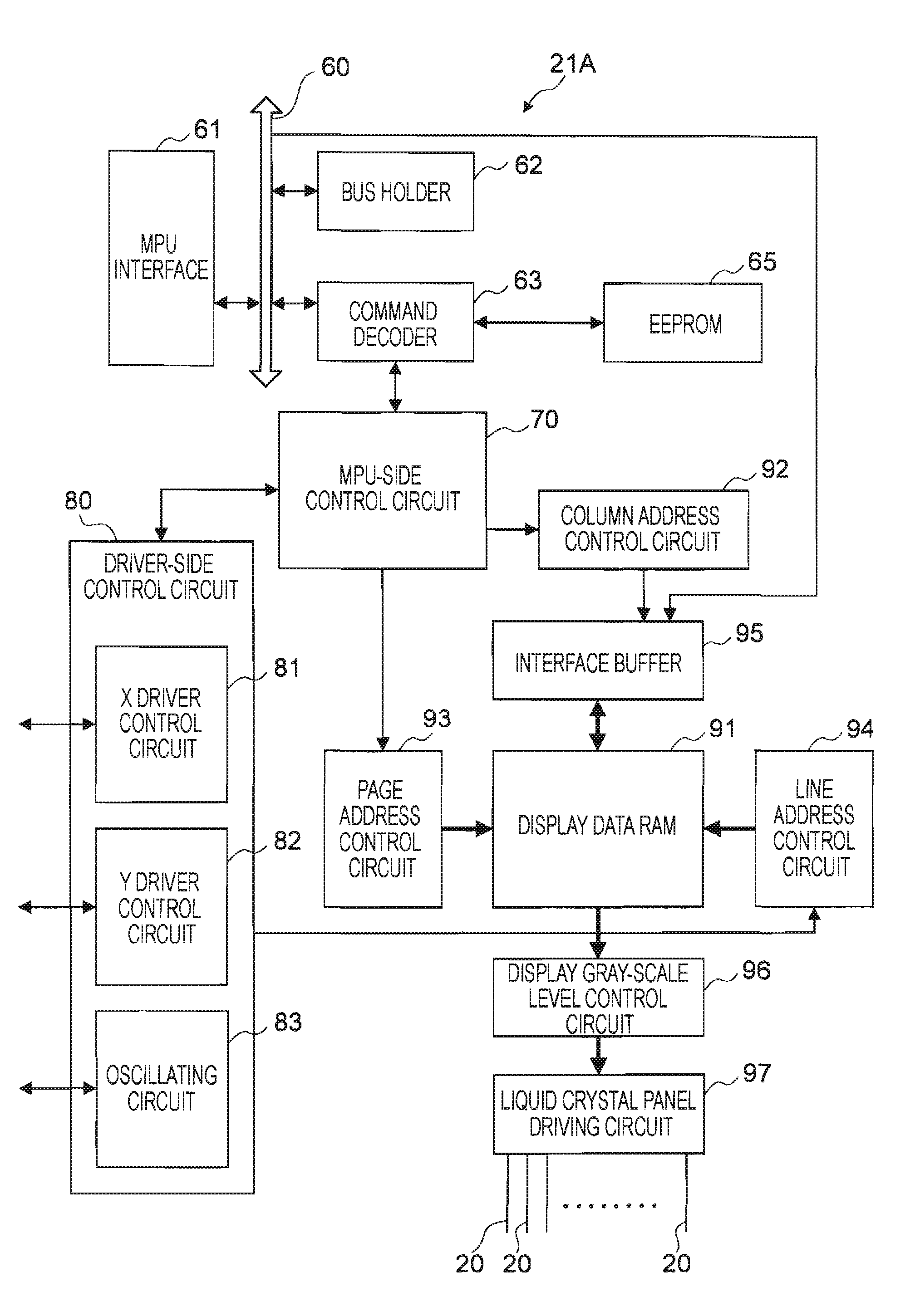
[0047]FIG. 1 is a block diagram illustrating an electro-optical device 1 according to a first embodiment of the invention.

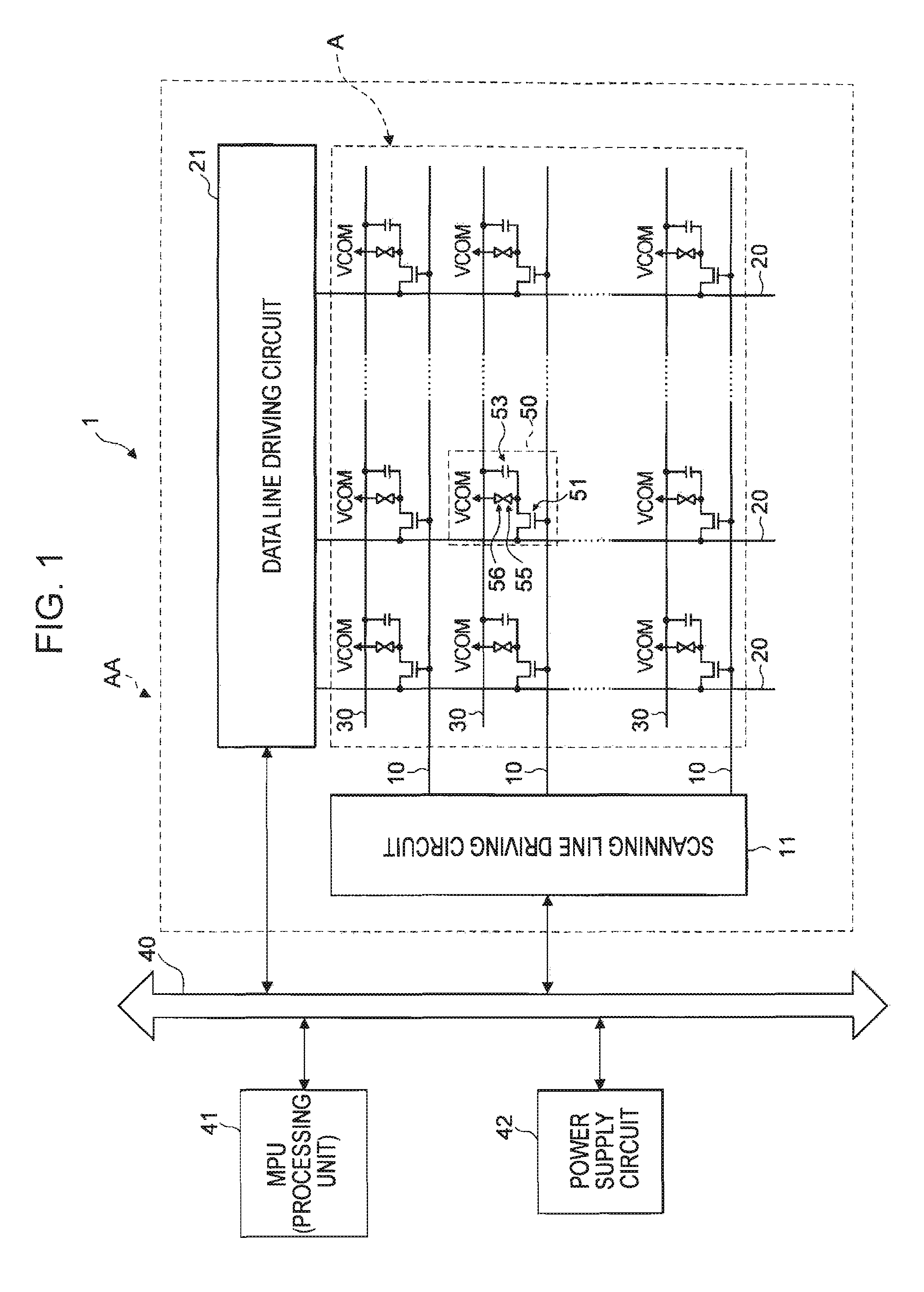
[0048] The electro-optical device 1 includes a liquid crystal panel AA, a scanning line driving circuit 11 and a data line driving circuit 21 that drive the liquid crystal panel AA, an MPU (microprocessor unit) 41, and a power supply circuit 42.

[0049] The MPU 41 is connected to an external bus 40 and controls the scanning line driving circuit 11, the data line driving circuit 21, and the power supply circuit 42.

[0050] Specifically, the MPU 41 supplies vertical synchronization signals and horizontal synchronization signals to the scanning line driving circuit 11 and the data line driving circuit 21, and issues various commands to those circuits. Further, the MPU 41 sets the voltage level of the power supplied to the power supply circuit 42.

[0051] On the basis of a reference voltage supplied from the outside, the power supply circuit 42 generates various power ...


PUM


Abstract

An electro-optical device includes: a plurality of scanning lines; a plurality of data lines; and a plurality of pixels that are provided at positions corresponding to intersections of the scanning lines and the data lines and include pixels each having a red color filter and pixels each having a blue color filter. A plurality of frames are set as a reference frame, the pixels are displayed with either a first gray-scale or a second gray-scale whose level is higher than that of the first gray-scale by one gray-scale level, in each frame, and image signals are supplied to the plurality of data lines such that adjacent pixels nave phases opposite to each other at a spatial frequency among the pixels each having the red color filter and the pixels each having the blue color filter.

Description

BACKGROUND [0001] 1. Technical Field [0002] The present invention relates to an electro-optical device using an electro-optical material, such as liquid crystal, to a method of driving the electro-optical device, and to an electronic apparatus having the electro-optical device. [0003] 2. Related Art [0004] Electro-optical devices, such as liquid crystal devices, which display images, have been known. An electro-optical device includes a first substrate, a second substrate provided to face the first substrate, and liquid crystal provided between the first and second substrates so as to control the light emitted from a backlight. The first substrate has a backlight, a plurality of scanning lines, a plurality of data lines, and a plurality of pixel electrodes and switching elements that are provided at positions corresponding to intersections of the scanning lines and the data lines. [0005] In the electro-optical device, a display region, which is composed of a plurality of pixels that...

Claims


Application Information

Patent Timeline
Patent Type & Authority Applications(United States)
IPC IPC(8): G09G3/36
CPCG09G3/2003G09G3/2055G09G2300/0452G09G3/3611G09G3/3607
Inventor KURUMISAWA, TAKASHIMORIYA, HIDEKUNI
Owner SEIKO EPSON CORP
Why Eureka
Try Eureka