Heat dissipation device having power wires fixture

a heat dissipation device and power wire technology, which is applied in the installation of lighting conductors, electrical apparatus casings/cabinets/drawers, and coupling device connections, etc., can solve the problems of reducing the disassembly efficiency of the heat dissipation apparatus in the computer, contaminating the wires with dust and dirt, and deteriorating the appearance of the wires

Inactive Publication Date: 2007-03-15
FU ZHUN PRECISION IND SHENZHEN +1
View PDF17 Cites 3 Cited by
  • Summary
  • Abstract
  • Description
  • Claims
  • Application Information

AI Technical Summary

Benefits of technology

[0005] In the heat dissipation apparatus, some of the adhesive still sticks to the wires after the tape is peeled off the heat dissipation apparatus. The remained adhesive on the wires may deteriorate the appearance of the wires and contaminate the wires with dusts and dirt. In conventional operation, the remained adhesive needs to be removed from the wires before the heat dissipation apparatus is mounted in a computer, which decreases disassembly efficiency of the heat dissipation apparatus in the computer. Thus, a fixture which can secure power wires of a fan of a heat dissipation apparatus at a fixed position during transportation of the heat dissipation apparatus, and which does not leave adhesive on the wires when the fixture is removed from the wires to release the wires is needed.

Problems solved by technology

The remained adhesive on the wires may deteriorate the appearance of the wires and contaminate the wires with dusts and dirt.
In conventional operation, the remained adhesive needs to be removed from the wires before the heat dissipation apparatus is mounted in a computer, which decreases disassembly efficiency of the heat dissipation apparatus in the computer.

Method used


Image

  • Heat dissipation device having power wires fixture
  • Heat dissipation device having power wires fixture
  • Heat dissipation device having power wires fixture

Examples


Embodiment Construction

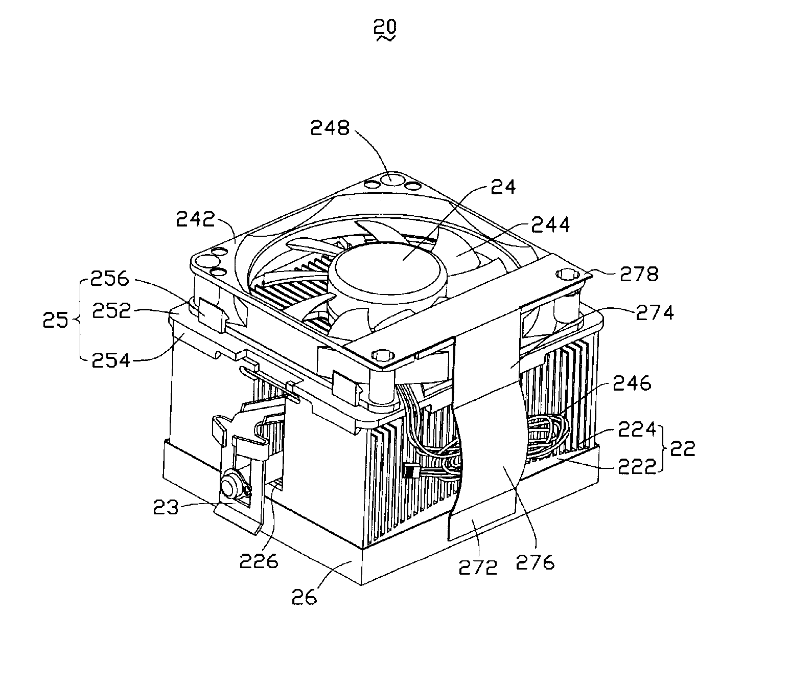
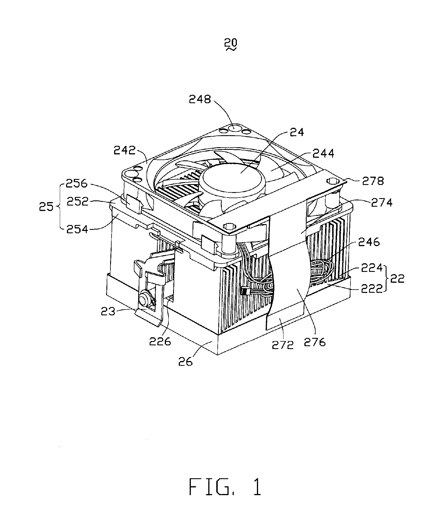
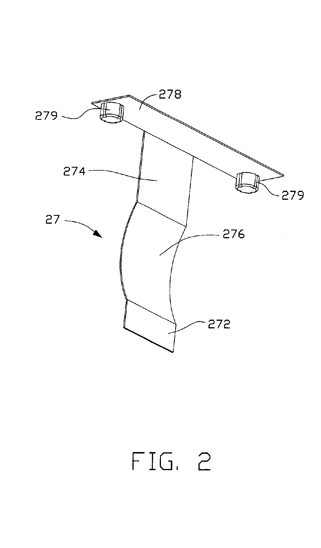
[0011] Referring to FIG. 1, a heat dissipation apparatus 20 for timely removing heat generated by a heat-generating electronic component (not shown) includes a heat sink 22, a clip 23, a heat-dissipating fan 24, a bracket 25, a grease protecting cover 26 and a wire fixture 27 (FIG. 2).

[0012] The heat sink 22 includes a rectangular shaped base 222, and a plurality of fins 224 mounted on the base 222. A bottom surface of the base 222 spreads a layer of thermal grease (not shown) thereon, for benefiting a thermally contact between the heat sink 22 and the heat-generating electronic component. The grease protecting cover 26 is intimately attached to the base 222 of the heat sink 22 for isolating the thermal grease from surrounding articles such as dusts and dirt, thereby preventing the thermal grease from being contaminated by the surrounding articles. A channel 226 extending through the fins 224 is defined at a middle portion of the heat sink 22. The clip 23 is received in the channel...


PUM


Abstract

A wire fixture (27) is for fastening power wires (246) of a heat-dissipating fan (24) to a supporting surface of a heat dissipation device (20). The heat dissipation device is for dissipating heat from a heat-generating electronic component. The wire fixture includes a catching portion (278) for being attached to an end of the supporting surface, a fixing portion (272) disposed with adhesive thereon, for being fixed to an opposite end of the supporting surface, and a covering portion (276) formed between the catching portion and the fixing portion and being without adhesive spread thereon, for urging the power wires of the heat dissipating fan to the supporting surface. The catching portion is without adhesive thereon.

Description

CROSS-REFERENCES TO RELATED APPLICATION [0001] This application is related to co-pending U.S. patent application Ser. No. 11 / 308,115, filed on Mar. 7, 2006, assigned to the same assignee as this application, and entitled "HEAT DISSIPATION DEVICE HAVING POWER WIRES FIXTURE". The disclosure of the above-identified co-pending application is incorporated herein by reference.FIELD OF THE INVENTION [0002] The present invention relates generally to a heat dissipation device, and particularly to a heat dissipation device having a fixture for attaching power wires of a heat dissipating fan of the heat dissipation device to a heat sink thereof. DESCRIPTION OF RELATED ART [0003] A heat dissipation apparatus always includes a heat dissipating fan. In transportation of the heat dissipation apparatus, power wires of the heat dissipating fan needs to be fixed to the heat dissipation apparatus, for facilitating handling of the heat dissipation apparatus during the transportation. [0004] In nowadays...

Claims


Application Information

Patent Timeline
Patent Type & Authority Applications(United States)
IPC IPC(8): H05K7/20
CPCH01L23/467H01L2924/0002Y10T24/141Y10T24/14H01L2924/00
Inventor YU, FANG-XIANG
Owner FU ZHUN PRECISION IND SHENZHEN
Why Eureka
Try Eureka