Socket device

Inactive Publication Date: 2007-03-15
MORIYAMA SANGYO
View PDF17 Cites 41 Cited by
  • Summary
  • Abstract
  • Description
  • Claims
  • Application Information

AI Technical Summary

Benefits of technology

[0014] As described above, because the socket device of the present invention comprises a cap, various functions can be easily achieved by attaching different caps. For example, in the case where an LED is mounted in the socket main body, a light-transmissive cap may be attached for protecting and holding the LED. Also, it may be possible to form a connector for establishing connection to outside apparatus by providing the cap with a pair of electroconductive terminals and externally extending cords attached to the terminals so that when the cap is attached to the socket, the electroconductive terminals of the cap contact the corresponding conductors held by the socket.
[0015] If the cap attached to the socket main body presses the electric element against the conductors so that the electric element and the conductors are press-contacted to each other, a reliable electrical contact between the electric element and conductors can be preferably achieved while preventing the electric element from being removed inadvertently out of the socket main body or rattling in the socket main body. By pressing the electric element against the conductors to achieve the electric connection therebetween, it is possible to eliminate need for welding or soldering the electric element to the conductors. This can allow the electric element to avoid being affected by thermal history that could result if the electric element is passed through a reflow furnace or the like.
[0016] The cap main body equipped with an optical function part for processing and/or controlling the light emitted from the light emitting element (3, 13, 22) allows easy processing/controlling of the light such as convergence, divergence, reflection, refraction, color change, etc. Also, selective use of caps of different optical functions can achieve various illumination effects easily. The provision of moveable structure to the optical function part enables an optical function property (e.g., direction of irradiated light) to be changed easily.
[

Problems solved by technology

However, the forming and bending of such a tongue piece in the conductor can make the manufacturing

Method used


Image

  • Socket device
  • Socket device
  • Socket device

Examples


Embodiment Construction

[0021] Now the present invention is described in the following in terms of concrete embodiments with reference to the appended drawings. It should be noted that common component parts are denoted with same reference numerals throughout the drawings.

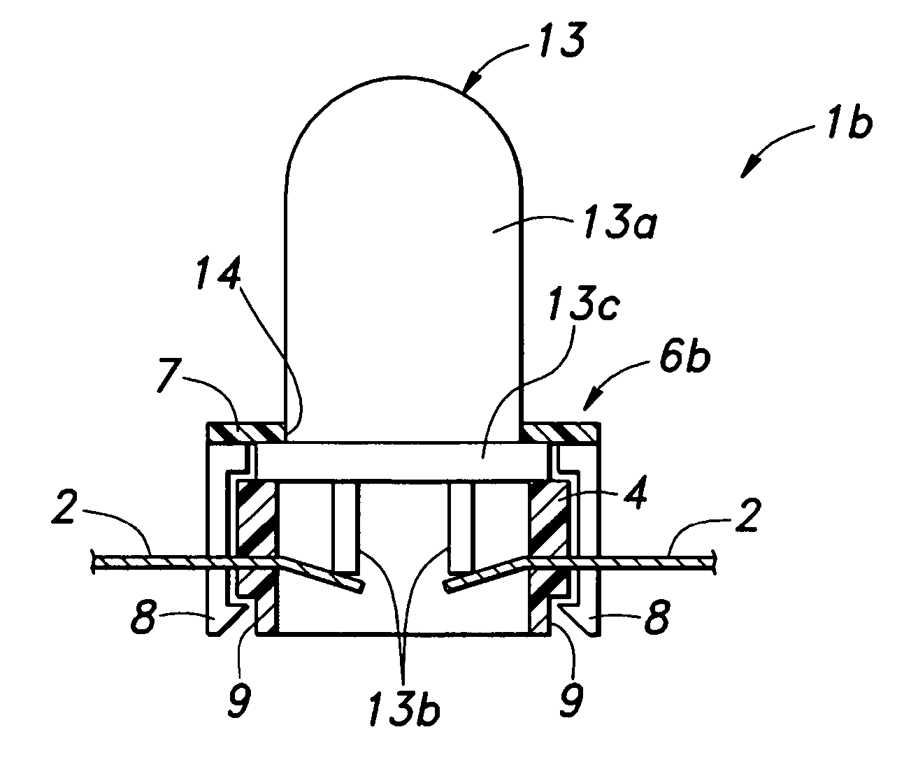
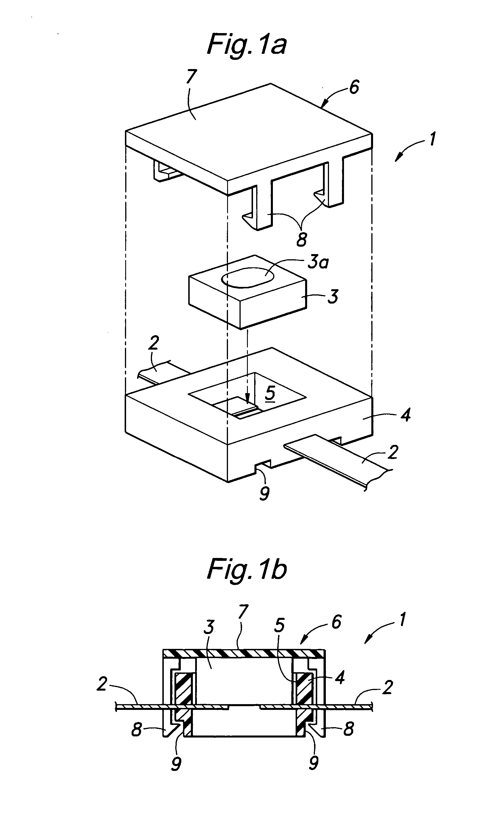
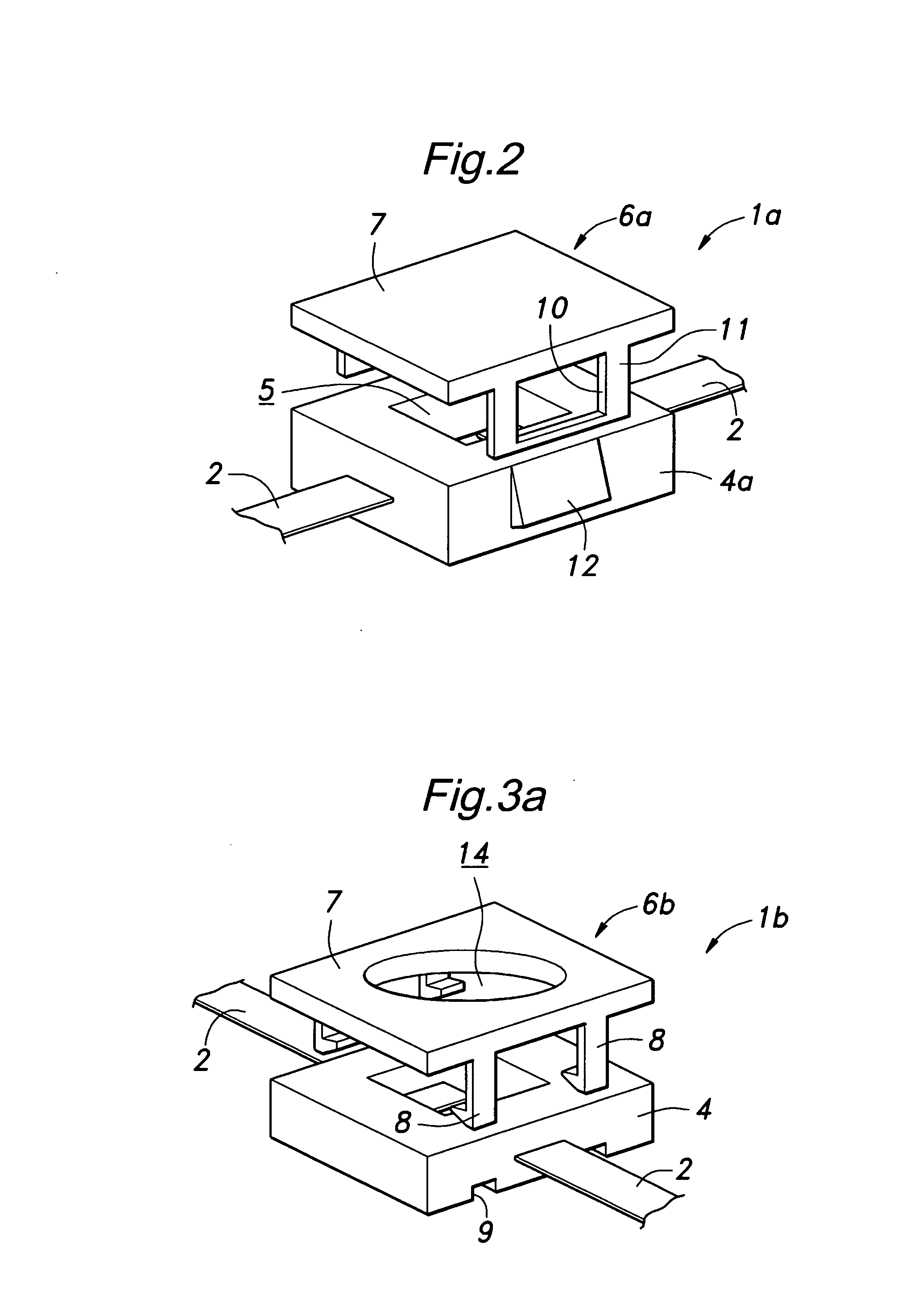
[0022]FIG. 1 is an exploded perspective view showing an embodiment of the socket device according to the present invention, and FIG. 2 is a cross-sectional view showing an assembled state of the socket device. The illustrated socket device 1 comprises a plurality of plate-shaped conductors 2 and a chip-type LED 3 as a light source (light emitting element) electrically connected to the conductors 2 to implement a light emitting device. In this embodiment, the LED 3 has a light emitting part 3a on its top and a pair of contacts (not shown) for electric connection on its bottom. It should be noted that though the drawings show only a pair of conductors 2 and one LED 3, the number of conductors 2 and LEDs 3 can be arbitrary, and a plurality ...


PUM


Abstract

There is provided a socket device (1, 1a-1g), comprising a plurality of conductors (2); a socket main body (4) coupled to the conductors to hold them together and defining a cavity (5) having an opening at least in one surface to expose part of the conductors so that an electric element (3, 13, 22, 40) can be connected to the conductors exposed in the cavity; and a cap (6, 6a-6n, 6p) having a cap main body (7) for covering at least part of the one surface of the socket main body and attached to the socket main body.

Description

TECHNICAL FIELD [0001] The present invention relates to a socket device that is attached to conductors for mounting a light emitting diode (LED) or the like. BACKGROUND ART [0002] It has been proposed to manufacture a light emitting device comprising a plurality of LEDs by attaching the LEDs to a patterned conductor formed with a circuit by, e.g., patterning (or press working) a plate-shaped conductor, instead of using a printed circuit board (see Patent Document 1, for instance). In this document, it is disclosed to use electrically insulating sockets formed by molding, etc. so as to be integrally coupled to the conductors for the purpose of holding or positioning the LEDs. The socket defines a cavity with an opening on its top to expose the conductors to which the LED is to be attached, and the LED is held in the cavity. In order to achieve reliable electric connection of the LED and prevent faulty connection, it is proposed in the above document to make a cut in part of the condu...

Claims


Application Information

Patent Timeline
IPC IPC(8): F21V15/00F21V8/00F21V14/06F21V15/01F21V17/16F21V19/00H01L33/58H01R13/627H01R33/05H01R33/09H05K3/30
CPCF21S8/033F21S8/04F21V14/06F21V15/01F21V17/164F21V19/001F21W2121/006G02B6/0008G02B6/0033H01L33/58H01R13/6273H01R33/09H05K3/301F21Y2101/02F21Y2115/10
Inventor MORIYAMA, HIDEOHOSHIKAWA, KIYOTOSHI
Owner MORIYAMA SANGYO
Why Eureka
Try Eureka