
Monitoring device for image forming device, control method and control program of monitoring device, and computer-readable storage medium

a monitoring device and image forming technology, applied in the direction of instruments, electrographic process devices, optics, etc., can solve the problems of inability to estimate the profit the administrator of the image forming device gains from and the profit rate of the administrator of the image forming device decreases, so as to facilitate comprehend the profit scale of the image forming service

Inactive Publication Date: 2007-03-15
SHARP KK
View PDF16 Cites 5 Cited by
  • Summary
  • Abstract
  • Description
  • Claims
  • Application Information

AI Technical Summary

Benefits of technology

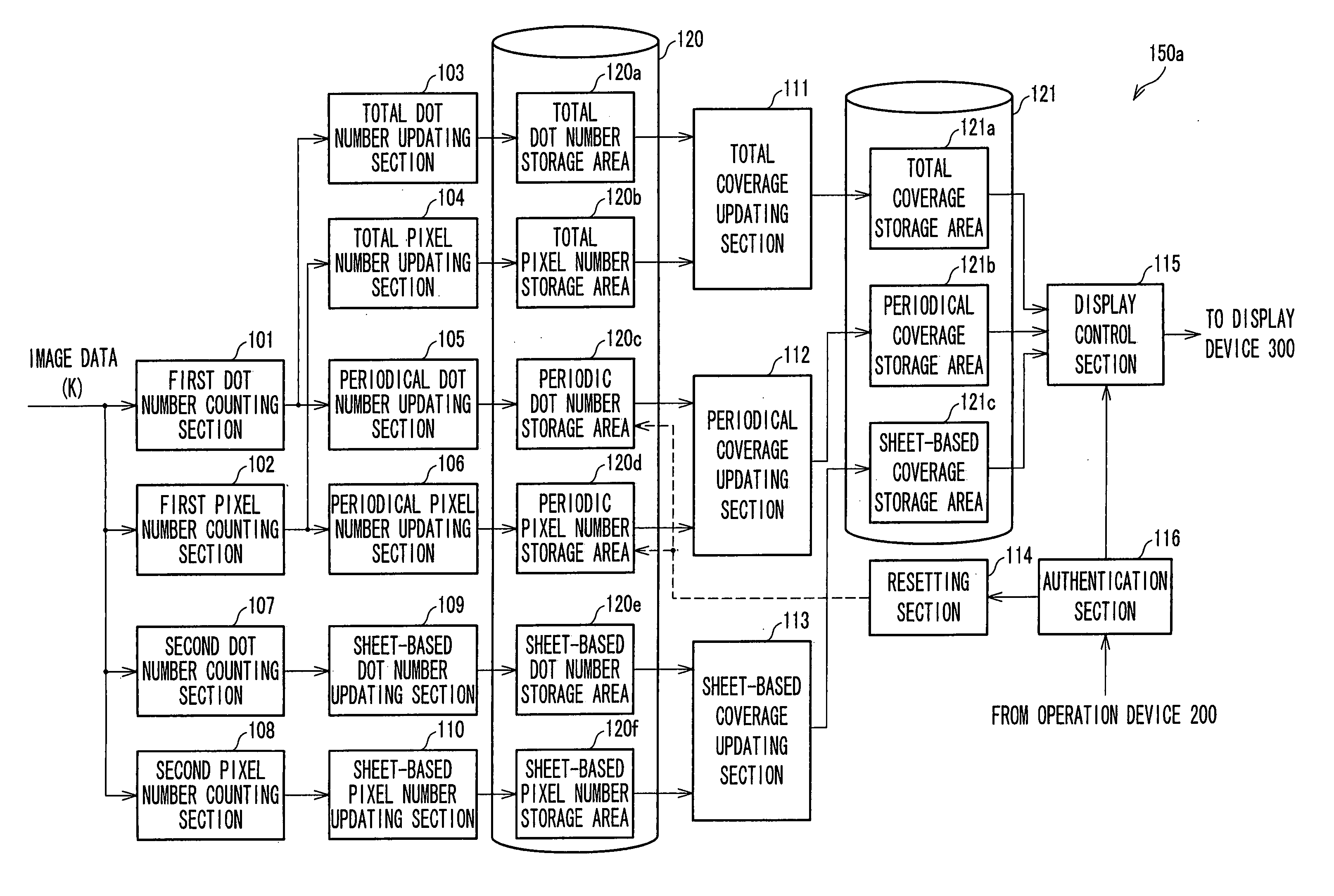
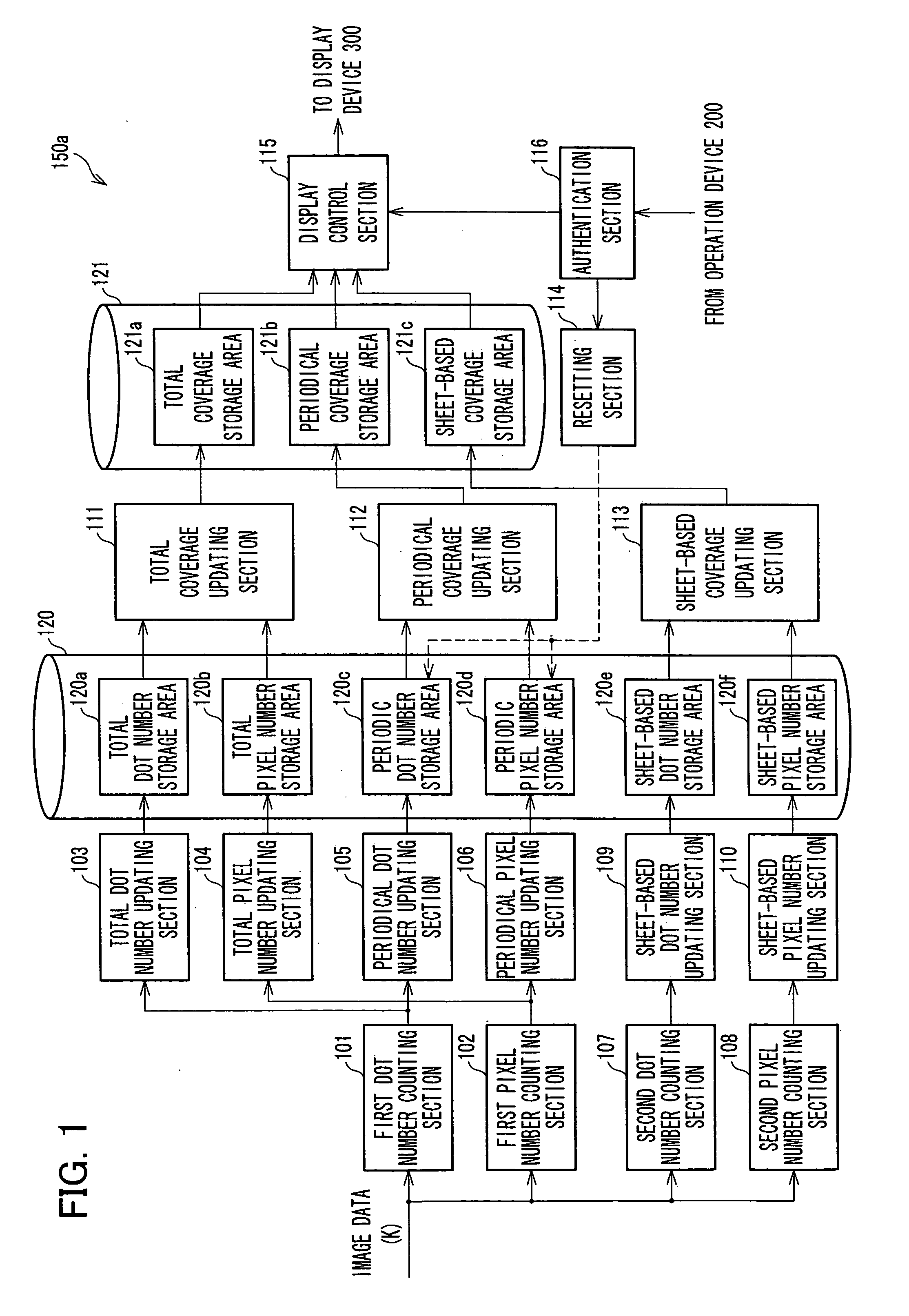
[0007] The present invention is made in view of the foregoing conventional problem, and an object is to provide a monitoring device for an image forming device with a function of allowing the user to easily comprehend a profit scale of an image forming service.
[0009] This structure allows the administrator of the image forming device to accurately comprehend the degree of toner consumption from an arbitrary time point to the present time. In other words, the monitoring device allows the administrator of the image forming device to comprehend the degree of toner consumption during a specific recent period, enabling the administrator to figure out an accurate profit rate gained by the image forming device in the period.

Problems solved by technology

On the other hand, the profit which the administrator (service provider, service supporting company) of the image forming device gains from the image forming service cannot be estimated only from the number of sheets consumed, because the consumption of toner is also relevant to the cost.
More specifically, if the toner consumption is higher than the expected amount for the number of sheets, the profit rate of the administrator of the image forming device decreases.

Method used


Image

  • Monitoring device for image forming device, control method and control program of monitoring device, and computer-readable storage medium
  • Monitoring device for image forming device, control method and control program of monitoring device, and computer-readable storage medium
  • Monitoring device for image forming device, control method and control program of monitoring device, and computer-readable storage medium

Examples


Embodiment Construction

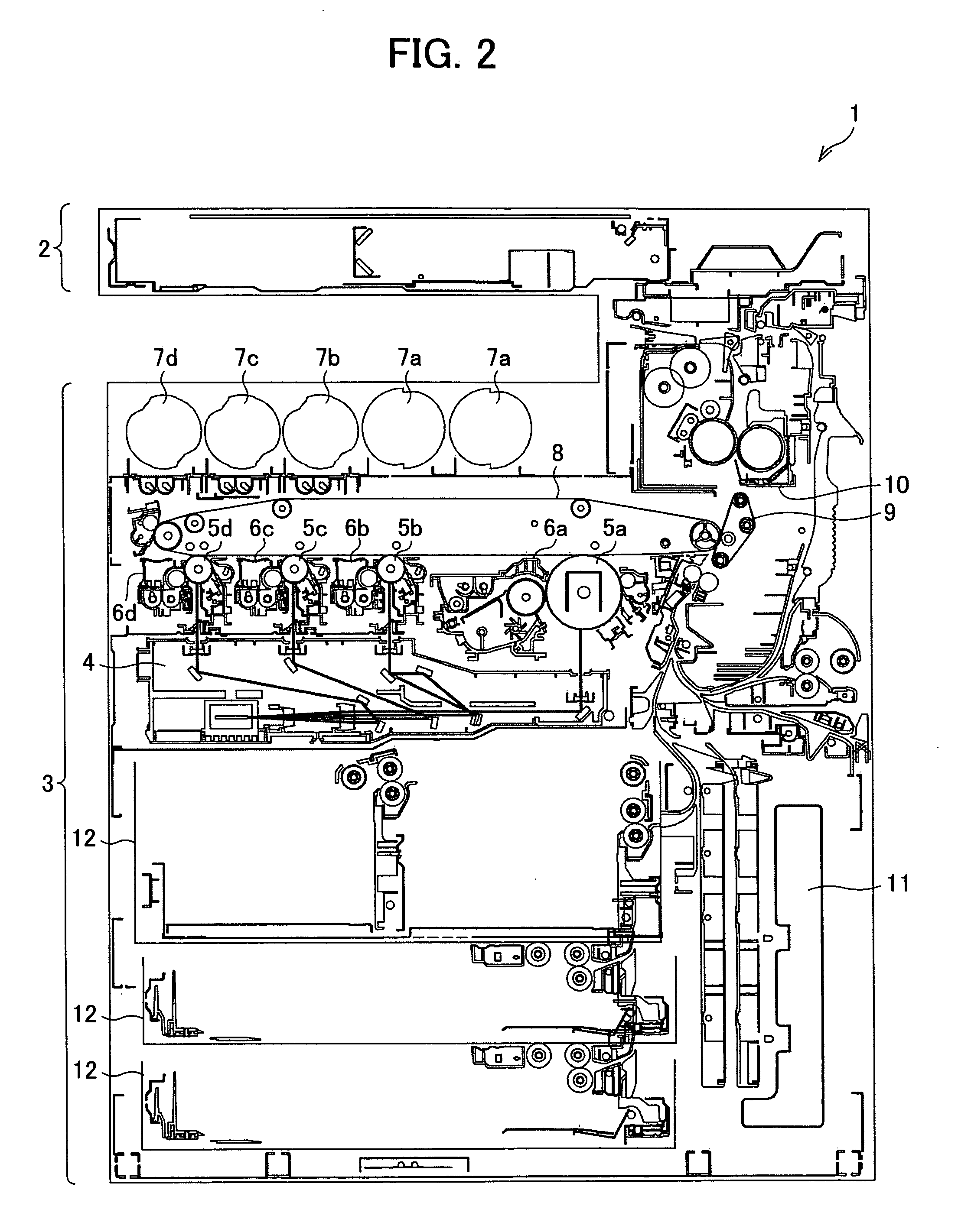
[0021] The following explains a monitoring device according to one embodiment of the present invention with reference to Figures. The explanation first deals with an MFP (Multi Function Printer) to which the monitoring device is mounted. FIG. 2 is a vertical cross-sectional view of an MFP.

[0022] As shown in FIG. 2, an MFP (image forming device) 1 includes a document scanning device (scanner) 2 for outputting image data scanned from a document by a CCD (charge Coupled Device), and a printer 3 for forming (printing) an image on a paper sheet based on the image data.

[0023] The printer 3 is a tandem digital color printer of electrophotographic mode. The printer 3 mainly includes an exposure unit (laser scanner unit) 4, photoconductive drums 5, developing devices 6, toner boxes 7, intermediate transfer belt 8, and a secondary transfer unit 9, a fixing unit 10, a waste toner box 11, and a paper feeding cassette 12.

[0024] The image data processed in the MFP corresponds to a multi color ...


PUM


Abstract

Provided is a coverage monitor for monitoring a utilization scale of an MFP which forms an image on a sheet with color toner. The coverage monitor comprises: (i) a periodic coverage updating section for generating a periodic coverage which denotes a coverage from a certain time point, which is specified by an administrator of the MFP, to a present time, based on image data expressing the image; and (ii) a display control section for displaying the periodic coverage so that the administrator can visually confirm the coverage. The coverage monitor enables the administrator to easily comprehend the profit rate.

Description

[0001] This Nonprovisional application claims priority under 35 U.S.C. § 119(a) on Patent Application No. 2005-264474 filed in Japan on Sep. 12, 2005, the entire contents of which are hereby incorporated by reference. FIELD OF THE INVENTION [0002] The present invention relates to a monitoring device which is capable of monitoring utilization scale of an image forming device, and also relates to a control method and a control program of the monitoring device, and a computer readable storage medium. BACKGROUND OF THE INVENTION [0003] In a general image forming service using an image forming device such as a photocopier or a printer, the number of photocopied documents or printed sheets is counted by a counter, and the user is charged for the amount found by multiplying the number by an amount per sheet. [0004] In a general image forming service using an image forming device such as a photocopier, or a printer, the number of photocopied documents or printed sheets is counted by a count...

Claims


Application Information

Patent Timeline
Patent Type & Authority Applications(United States)
IPC IPC(8): G03G21/02
CPCG03G15/553G03G15/5075G03G15/55G03G21/02
Inventor SAKITA, HIROFUMIIZUMI, HIROKAZUNISHIMURA, HIDEYUKIKOBAYASHI, HISAAKI
Owner SHARP KK
Learn More