
Batch deposition tool and compressed boat

a technology of deposition tool and boat, which is applied in the direction of conveyor parts, thin material processing, electrical equipment, etc., can solve the problems of increasing the pumping volume of the chamber, the difficulty of uniform gas delivery and heat transfer in the batch processing chamber, etc., and achieves the effect of compressing the boat and less spa

Inactive Publication Date: 2007-03-15
APPLIED MATERIALS INC
View PDF22 Cites 20 Cited by
  • Summary
  • Abstract
  • Description
  • Claims
  • Application Information

AI Technical Summary

Benefits of technology

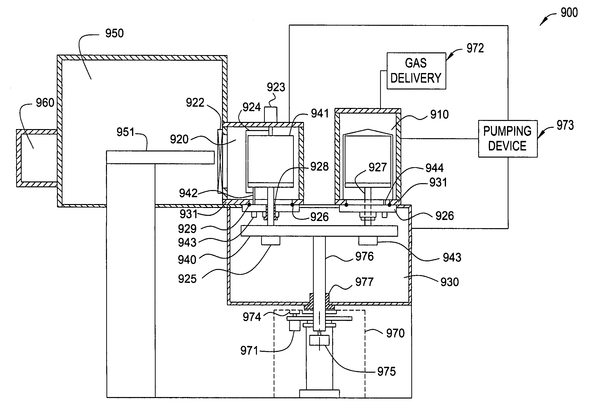
[0012] One embodiment of the present invention relates to a compressed boat in a batch processing chamber. The compressed boat comprises a first substrate boat configured to receive and support substrates on a first plurality of parallel planes and a second substrate boat configured to receive and support substrates on a second plurality of parallel planes. The compressed boat further comprises a connecting mechanism configured to movably connect the first substrate boat and the second substrate boat, wherein the compressed boat has an open position and a closed position, wherein in the closed position the first plurality of parallel planes are interleaving with the second plurality of parallel planes and wherein in the open position the first and second substrate boats can be loaded and unloaded independently. This configuration compresses the boat size by requires less space between substrates during processing in the closed position.

Problems solved by technology

Uniform gas delivery and heat transfer in a batch processing chamber is more difficult to achieve than in a single substrate system.
However, including susceptors usually increases the pumping volume of the chamber.

Method used


Image

  • Batch deposition tool and compressed boat
  • Batch deposition tool and compressed boat
  • Batch deposition tool and compressed boat

Examples


Embodiment Construction

[0037] The present invention generally provides an apparatus and method for batch processing that would reduce cost of ownership (COO).

[0038] In some embodiments of the invention, reducing the volume of a batch processing chamber without reducing the number of substrates results in improved COO. Reducing the volume of a batch processing chamber reduces the usage of precursor gases and / or other processing materials. Furthermore, reducing the volume of an ALD batch processing chamber reduces the time it takes to assure that all of the surfaces are saturated with processing gases.

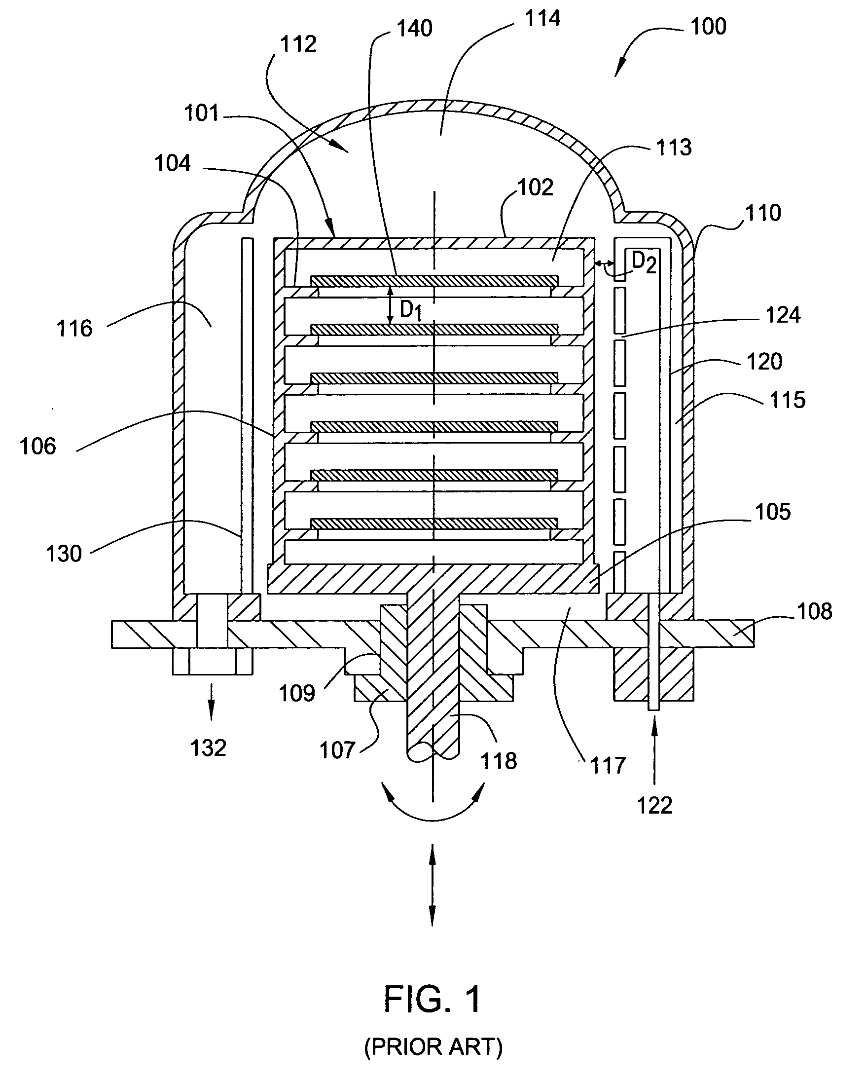
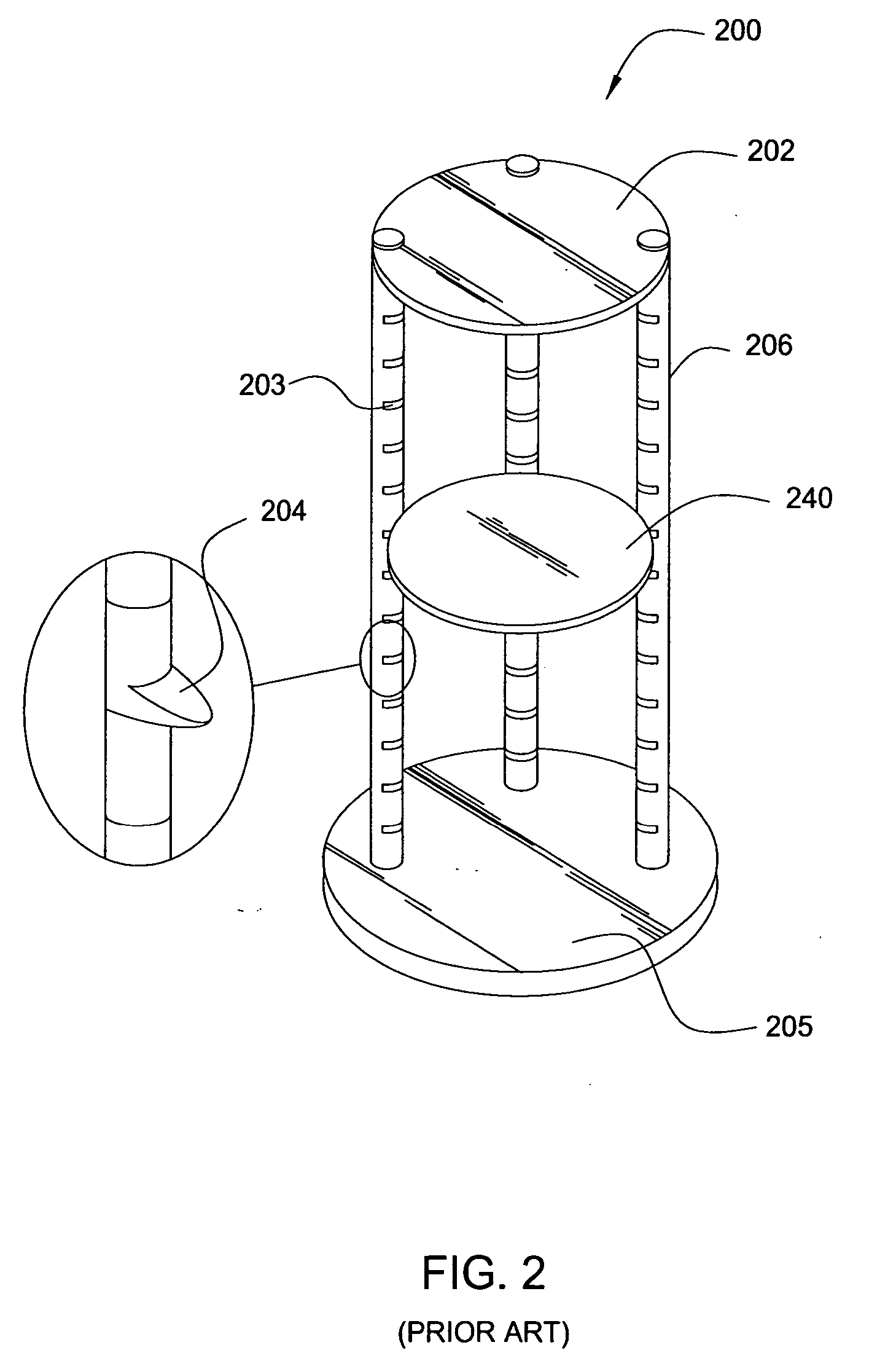
[0039] In one aspect, reducing the size of a substrate boat is most effective in reducing the volume of a batch processing chamber. Referring to FIG. 1, the substrate boat 101 occupies the majority of the vacuum volume 112. Key factors determining the boat size generally include a distance D1 between each substrate 140 and its upper susceptor 104 and a distance D2 between the susceptors 104 and the chamber w...


PUM


Abstract

Aspects of the invention include methods and apparatus for processing a batch of substrates. In one embodiment, a compressed substrate boat is configured to reduce pumping volume in a batch processing chamber. The compressed substrate boat comprises a stationary substrate boat and a movable substrate boat, each may be loaded / unloaded independently. The movable substrate boat and the stationary substrate boat may be interleaving with one another such that the distance between the substrates is reduced. In another embodiment, a substrate boat having removable substrate holder is configured to provide susceptors without dramatically increasing pumping volume. The removable substrate holder may be loaded / unloaded away from the substrate boat with susceptors. The removable substrate holder is engaged with the substrate boat such that substrates thereon are interleaving with the susceptors. Embodiments of the present invention reduces pumping volume and increases throughput, hence reduces cost of ownership during batch processing.

Description

BACKGROUND OF THE INVENTION [0001] 1. Field of the Invention [0002] Embodiments of the invention generally relates to methods and apparatus of supporting and transferring substrates and reducing pumping volume during batch processing. Embodiments of the invention also relates to methods and apparatus of uniform gas delivery and uniform heat transferring in a batch processing chamber. [0003] 2. Description of the Related Art [0004] The effectiveness of a substrate fabrication process is often measured by two related and important factors, which are device yield and the cost of ownership (COO). These factors are important since they directly affect the cost to produce an electronic device and thus a device manufacturer's competitiveness in the market place. The COO, while affected by a number of factors, is greatly affected by the number of substrates produced per hour. Batch processing is often very effective improving COO by substantially increasing the number of substrates without ...

Claims


Application Information

Patent Timeline
IPC IPC(8): H01L21/677
CPCH01L21/67757H01L21/67309H01L21/6773Y10S414/14
Inventor YUDOVSKY, JOSEPHCOOK, ROBERT C.MERRY, NIR
Owner APPLIED MATERIALS INC
Learn More